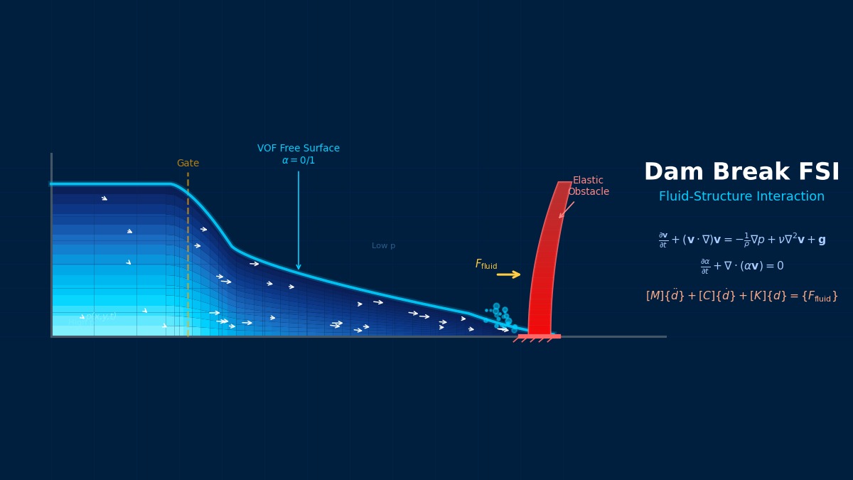
Dam Break Fluid-Structure Interaction
Overview
Professor, in what scenarios is FSI analysis for dam breaks used?
Dam Break Fluid-Structure Interaction: Theoretical Foundations
It is used for evaluating loads when flood waves from dam breaks collide with downstream buildings and structures, predicting impact forces of tsunamis on breakwaters and buildings, and assessing sloshing impact forces during liquid storage tank failures. Its characteristic is the ability to simultaneously handle unsteady fluids with free surfaces and large deformations of structures.
The presence of a free surface is what differentiates it from ordinary FSI, right?
Exactly. Because it's the coupling of free-surface gas-liquid two-phase flow with structures, the computation becomes more complex than ordinary single-phase FSI. The effects of wave breaking and entrapped air are also important and significantly influence the impact pressure.
Governing Equations
Please tell me the equations on the fluid side.
It combines the incompressible Navier-Stokes equations with free surface tracking. The VOF (Volume of Fluid) method is the most common.
$\alpha$ is the VOF function, where $\alpha = 1$ is liquid and $\alpha = 0$ is gas. Material properties are mixed using $\rho = \alpha \rho_l + (1-\alpha)\rho_g$.
How is the structure side handled?
For elastic structures, standard FEM. Concrete for the dam body uses an elastoplastic model; for downstream buildings that may break, coupling with SPH (Smoothed Particle Hydrodynamics) or DEM (Discrete Element Method) is sometimes used.
The structural equation of motion is in the standard form.
$\{F_{fluid}\}$ is the pressure load and viscous force from the fluid to the structure, obtained by integration at the coupling interface.
Since it's an impact load, is an explicit method necessary?
Why Dam Break Became the "FSI Textbook"
The dam break problem is used worldwide as a verification benchmark for computational fluid dynamics. The wavefront propagation speed when water is suddenly released has an analytical solution (Ritter solution), making comparison with numerical calculations easy. Furthermore, adding impact forces when structures are present turns it into an FSI verification problem. Measured data were obtained from the 2005 Monte Testaccio dam collapse and used for verification of SPH and MPS methods. The theory is simple and verification is clear—that's why it's a benchmark loved by researchers worldwide.
Computational Methods for Dam Break Fluid-Structure Interaction
| Method | Characteristics | Application Scenarios |
|---|---|---|
| VOF | Tracks volume fraction on Eulerian mesh | General-purpose, large-scale computation |
| Level Set | Tracks interface using distance function | Smooth interfaces |
| SPH | Mesh-free particle method | Wave breaking, spray |
| MPS (Particle Method) | Improved SPH version, incompressible | Originated in Japan, nuclear reactor safety |
| ALE | Mesh follows the interface | Small interface deformation cases |
For intense free-surface flows like dam breaks, VOF or SPH are mainstream.
How is coupling with structures done in SPH?
SPH-FEM coupling is used. Fluid is represented by SPH particles, structure by FEM elements, and loads are transmitted via contact algorithms. LS-DYNA's DEFINE_SPH_TO_SPH_COUPLING or CONSTRAINED_LAGRANGE_IN_SOLID are representative implementations.
OpenFOAM for Dam Break FSI
What about implementation with open source?
One method is combining OpenFOAM's interDyMFoam (VOF + Dynamic Mesh) with solids4foam (structural solver). Another popular approach is coupling OpenFOAM (fluid) with CalculiX (structure) via preCICE.
The basic equation for interFoam is Navier-Stokes with VOF, using the MULES algorithm to maintain a sharp interface.
Impact Pressure Evaluation
How can we ensure the accuracy of impact pressure?
Impact pressure strongly depends on the compressibility of entrapped air. Incompressible VOF assumptions can sometimes overestimate peak impact pressure values.
As countermeasures, compressible VOF (compressibleInterFoam) or models artificially introducing air cushion effects are used. When comparing with experiments, it's necessary to recognize that pressure peak values have large variability (coefficient of variation 30-50%).
| Phenomenon | Impact Pressure Characteristics |
|---|---|
| Direct Impact (flip-through) | Extremely high short-duration peak (below 10ms) |
| Air Cushion Impact | Peak is somewhat lower but duration is longer |
| Run-up Load | Quasi-static, dominant in structural response |
So for evaluating structural response, not just the peak impact pressure but also its duration is important, right?
Exactly. The ratio of the structure's natural period to the load duration determines the dynamic amplification factor. For short-duration impacts, the structure cannot follow, so evaluation by impulse (force × time) is often more appropriate.
SPH and MPS—Why Particle Methods Shine in Dam Break Analysis
In large-deformation free-surface flows like dam breaks, the weakness of Eulerian/ALE methods—where meshes deform severely and fail—becomes apparent. This is where particle methods (SPH, MPS) come into play. Particle methods treat fluid as a collection of particles, eliminating the need for meshes and allowing them to handle large deformations and splashing. However, particle methods have higher computational costs and generally lower accuracy than mesh methods. In practice, hybrid methods that automatically switch between "particle methods for the initial violent collision phase with intense splashing" and "mesh methods for subsequent steady flow" are also being researched.
Dam Break Fluid-Structure Interaction in Practice
1. Initial Condition Setup: Water level (head difference), dam opening method (instantaneous, gradual)
2. Computational Domain Design: Sufficient area including downstream structures. At least 30 times the dam height in horizontal direction.
3. Mesh Generation: Refine impact area. Minimum 10 cells per water depth for free surface resolution.
4. Boundary Conditions: Bottom/walls: no-slip, top: atmospheric pressure open.
5. Time Step: CFL < 0.5 (for VOF accuracy), adaptive time step recommended.
6. Computation Execution: Track free surface with VOF while coupling with structure.
7. Postprocessing: Impact pressure time history, structural displacement/Stress, water level time variation.
Are there any benchmark problems for verification?
The following three are famous.
| Benchmark | Content | Experimental Data |
|---|---|---|
| Kleefsman (2005) | Dam break → obstacle impact | Pressure & water level time history |
| Lobovsky (2014) | Dam break → wall impact pressure | High-precision pressure measurement |
| Idelsohn (2008) | Dam break FSI on elastic wall | Wall displacement time history |
Mesh Convergence Verification
How should I decide the mesh fineness?
Impact pressure has very strong mesh dependency. Verify convergence with at least three levels (coarse, medium, fine). However, impact pressure peak values tend to increase with finer meshes and often do not strictly converge.
Practically, confirming that the pressure impulse (time-integrated value) becomes mesh-independent is a more robust approach. Directly verifying the convergence of structural response (displacement, maximum stress) is also a good approach.
Common Problems
Related Topics
| Problem |
|---|