Finite Volume Method Fundamentals
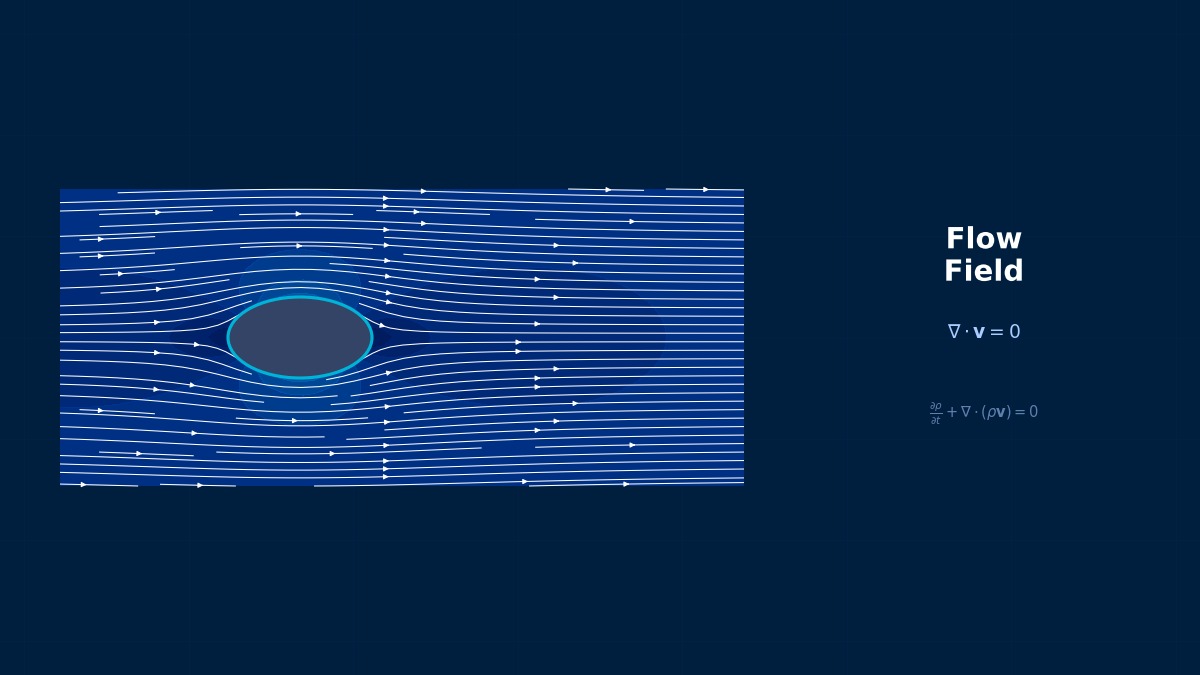
Theory: conservation as a balance over boxes
Overview
I hear almost every CFD code uses the finite volume method. What makes it so different from the finite element method we use for structures?
They start from different ideas. FEM multiplies the differential equation by weight functions and integrates over the whole domain (the weak form). FVM cuts space into small boxes — control volumes, or cells — and writes the balance directly: the rate of change inside a box equals what flows in through its faces minus what flows out, plus any source. Neighbouring boxes exchange exactly the same amount through their shared face, so mass cannot silently appear or vanish anywhere. That is the main reason it is preferred for fluid flow.
The integral transport equation
For a quantity $\phi$ (a velocity component, temperature, concentration, …) in a field with density $\rho$, velocity $\mathbf{u}$ and diffusivity $\Gamma$, conservation over a control volume $V$ with surface $S$ reads:
From left to right: unsteady, convection, diffusion and source terms. Replacing the surface integrals by sums over the faces $f$ of cell $P$ gives the discrete equation ($N$ is the neighbour across the face and $F_f$ the mass flux through it):
The equation looks simple. Where is the hard part?
The unknowns live at cell centres, but the equation needs face values $\phi_f$ and face gradients. How you interpolate from centres to faces largely decides accuracy and stability, and that is what the next sections are about.
Cell-centred and vertex-centred layouts
| Layout | Where unknowns live | Typical use |
|---|---|---|
| Cell-centred | Cell centres; each cell is a control volume | OpenFOAM, Ansys Fluent, Simcenter STAR-CCM+ |
| Vertex-centred | Mesh vertices, with a dual cell built around each vertex | e.g. Ansys CFX |
The book that spread heat-and-flow computing
S. V. Patankar's textbook “Numerical Heat Transfer and Fluid Flow” (1980) is often credited with bringing the finite volume method into engineering practice. It showed, step by step, how to assemble discrete equations from control-volume balances, together with the SIMPLE algorithm for correcting pressure and velocity alternately (published by Patankar and Spalding in 1972). Much of what runs inside today's commercial codes is a continuation of that book.
Discretisation: choosing face values
Diffusion: central differencing and non-orthogonal correction
The face gradient in the diffusion term is basically $(\phi_N-\phi_P)/|\mathbf{d}|$, the difference between the two cell centres. That is exact only when the vector $\mathbf{d}$ joining the centres is normal to the face. On non-orthogonal meshes a correction built from cell-centre gradients is added, usually treated explicitly, so strongly non-orthogonal meshes tend to make the iterations unstable.
Convection: choosing a scheme
| Scheme | Order | Behaviour |
|---|---|---|
| First-order upwind | 1st | Always bounded and robust; strong numerical diffusion smears gradients |
| Central differencing | 2nd | Oscillates when the cell Péclet number exceeds 2 |
| Second-order (linear) upwind | 2nd | Extrapolates with the upstream gradient; the practical default; can overshoot slightly |
| QUICK | 3rd (uniform grid) | Accurate but not guaranteed bounded |
| TVD (limited) | 2nd (1st near steep changes) | Switches towards upwind only near sharp changes to prevent wiggles |
The cell Péclet number
Whether convection or diffusion dominates is measured by the Péclet number based on the cell width $\Delta x$:
With central differencing the coefficient linking to the downstream neighbour is $D - F/2$, where $D=\Gamma/\Delta x$ and $F=\rho u$. When $Pe_\Delta>2$ it turns negative, which builds the unphysical rule “when upstream goes up, downstream goes down” into the equations. That is where the wiggles come from.
Worked example: 1D convection–diffusion
Steady convection–diffusion over $L=1$ m with $\rho=1$ kg/m³, $\Gamma=0.1$ kg/(m·s), $\phi=1$ at the left end and $\phi=0$ at the right has an exact solution, which makes it ideal for testing schemes:
Results for $u=2.5$ m/s ($Pe=25$) on 5 cells, i.e. a cell Péclet number of 5:
| x [m] | Exact | Central | 1st-order upwind |
|---|---|---|---|
| 0.1 | 1.0000 | 1.0356 | 0.9998 |
| 0.3 | 1.0000 | 0.8694 | 0.9987 |
| 0.5 | 1.0000 | 1.2573 | 0.9921 |
| 0.7 | 0.9994 | 0.3521 | 0.9524 |
| 0.9 | 0.9179 | 2.4644 | 0.7143 |
Maximum error as the number of cells increases under the same conditions:
| Cells | Cell Pe | Central | 1st-order upwind |
|---|---|---|---|
| 5 | 5 | 1.547 | 0.204 |
| 10 | 2.5 | 0.537 | 0.158 |
| 20 | 1.25 | 0.160 | 0.120 |
| 40 | 0.625 | 0.044 | 0.079 |
| 80 | 0.31 | 0.012 | 0.048 |
| 160 | 0.16 | 0.003 | 0.026 |
Central differencing on 5 cells gives 2.46 when the boundary values are 0 and 1. That's completely broken.
Yes — and the linear system is solved perfectly well, so the residuals won't warn you. Upwind never oscillates, but doubling the cells only cuts its error by about 1.7× (first order). Once the cell Péclet number drops below 2, central differencing cuts the error by about 4× per doubling (second order) and is more accurate from 40 cells on. Second-order upwind-type and TVD schemes are the practical default precisely because they avoid both weaknesses.
Pressure–velocity coupling
In incompressible flow there is no equation that determines pressure directly. The solver predicts a velocity from the momentum equations, then solves a pressure-correction equation so that continuity is satisfied and corrects both fields, and repeats. The SIMPLE algorithm (and its variant SIMPLEC) is common for steady runs and the PISO algorithm for transient ones.
- With velocity and pressure stored together at cell centres, pressure would develop a checkerboard pattern. Rhie–Chow interpolation of the face fluxes prevents it, and the major commercial codes do this internally.
- SIMPLE-type schemes need under-relaxation. Pressure 0.3 and momentum 0.7 are widely used starting values; lower them if the run diverges and raise them if convergence is too slow.
Practice: mesh and solver settings
Reading mesh quality
| Metric | What it harms | Guideline |
|---|---|---|
| Non-orthogonality | Diffusion accuracy and iteration stability | OpenFOAM checkMesh warns above 70°; tune the number and limiting of corrections |
| Skewness | Accuracy of face interpolation | checkMesh warns above 4 |
| Neighbour volume ratio | Gradient accuracy | Avoid abrupt size jumps; grade gradually |
| Aspect ratio | Accuracy when not aligned with the flow | Large values are fine in boundary layers with cells stretched along the flow |
Thresholds differ between tools, so treat these as guidelines and make the final judgement with the convergence checks below.
Judging convergence
- Don't stop just because residuals dropped three orders of magnitude. Check that the quantities you care about — pressure drop, lift, outlet temperature — have stopped changing.
- Check that the imbalance between inflow and outflow mass flow is small relative to the flow rate — for example below about 0.1%.
- Report final results with a second-order scheme. Use first-order upwind only to get the run started, then switch.
Settings in common tools
| Tool | Convection scheme | Pressure–velocity coupling |
|---|---|---|
| OpenFOAM | Write Gauss upwind, Gauss linearUpwind grad(U), Gauss linear, etc. under divSchemes in system/fvSchemes | Chosen by the solver (simpleFoam = SIMPLE, pimpleFoam = PIMPLE) |
| Ansys Fluent | Choose First Order Upwind, Second Order Upwind, QUICK, etc. under spatial discretisation | SIMPLE / SIMPLEC / PISO / Coupled |
| Simcenter STAR-CCM+ | Select the convection discretisation order in the physics models | Segregated or coupled flow solver |
The “false diffusion” of oblique flow
The numerical diffusion of first-order upwind is known to be largest when the flow crosses the mesh at 45°. Even with zero physical diffusion, a sharp interface travelling diagonally comes out blurred and widened. If this false diffusion exceeds the physical diffusivity, the result describes the mesh rather than the physics — a real concern whenever mixing or heat spreading is being assessed.
Common problems and verification
Symptoms and causes
| Symptom | Likely cause | Fix |
|---|---|---|
| Values beyond the boundary values, stripes | Central differencing at high cell Péclet number | Refine, or switch to linear upwind / TVD |
| Divergence within a few dozen iterations | Highly non-orthogonal cells, large relaxation factors | Fix those cells, lower relaxation, start with first order |
| Residuals stall at a plateau | The flow is genuinely unsteady (separation, vortex shedding) but solved as steady | If monitored quantities oscillate, switch to a transient run (time integration in CFD) |
| Results change a lot with the scheme | Mesh too coarse; numerical diffusion dominates | Do a mesh-convergence study first |
How to verify
- On a problem with an exact solution, like the 1D case above, check the observed order of accuracy — by what factor the error falls when the mesh is doubled.
- On real geometry, compare the quantity of interest on at least three meshes and estimate the discretisation error with Richardson extrapolation or the GCI (grid convergence index).
- Compare with experiments only after the discretisation error is known. Tuning a mesh-dependent result to match a test will fail under other conditions.
I'd like to reproduce the wiggles myself by changing the Péclet number.
With the convection-diffusion simulator you can vary velocity and diffusivity and find where central differencing starts to wiggle. The 1D finite volume simulator shows how control volumes are assembled, and the Thomas algorithm (TDMA) simulator shows how the resulting tridiagonal system is solved. A detailed comparison of schemes is in the article on upwind schemes.
Related Topics
Experience the theory firsthand with the interactive simulator for this field
All Simulators