Identification and Setting of Modal Damping
Identification and Setting of Modal Damping: Theoretical Foundations
What is Damping?
Professor, how is "damping" handled in structural mechanics?
Damping is the effect of dissipating vibrational energy. Without damping, a structure would vibrate forever. Real structures always have damping, which keeps the amplitude finite during resonance.
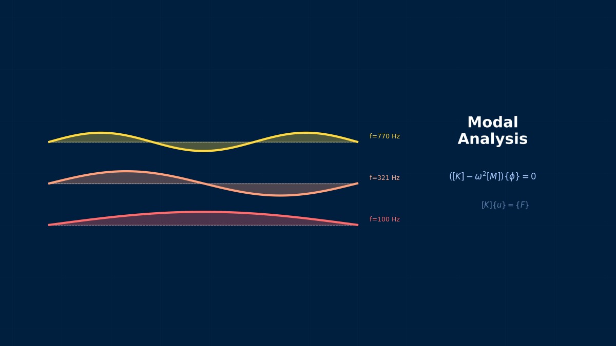
Equation of Motion
The equation of motion with damping:
$[C]$ is the damping matrix. $[M]$ and $[K]$ are physically clear, but $[C]$ generally has large uncertainty.
So the problem is how to determine the damping matrix.
Exactly. Damping modeling is the most uncertain parameter in FEM dynamic analysis.
Damping Models
Major damping models:
1. Modal Damping
Directly specify a damping ratio $\zeta_i$ for each mode. The most common method.
$q_i$ is the modal coordinate, $\omega_i$ is the natural angular frequency.
2. Rayleigh Damping
$[C] = \alpha [M] + \beta [K]$. $\alpha$ and $\beta$ are determined by matching $\zeta$ at two frequencies.
3. Structural Damping
Also called hysteretic damping. Frequency-independent damping, expressed with complex stiffness $[K^*] = [K](1 + ig)$. $g$ is the structural damping coefficient.
How do you choose which of the three models to use?
| Model | Application | Advantage | Disadvantage |
|---|---|---|---|
| Modal Damping | Mode superposition method | Different $\zeta$ for each mode | Requires modal analysis |
| Rayleigh Damping | Direct integration method (time history analysis) | Usable in time domain | Can only match $\zeta$ at two frequencies |
| Structural Damping | Frequency Response Analysis | No frequency dependence | Cannot be used in time domain |
Typical Damping Ratio Values
| Structure | Damping Ratio $\zeta$ |
|---|---|
| Steel Structure (welded) | 0.5–1% |
| Steel Structure (bolted) | 1–2% |
| RC Structure | 3–5% |
| Seismic Isolation Structure | 10–30% |
| Mechanical Structure | 1–3% |
| Composite Structure | 0.5–2% |
0.5–1% for steel structures... that's very small.
Steel has low internal damping. That's why steel structures are prone to large amplitudes at resonance, and damping settings greatly affect the results.
Summary
Let me organize the theory of modal damping.
Key points:
- Damping is the most uncertain parameter in dynamic analysis — sensitivity analysis is essential
- Three models — Modal damping, Rayleigh damping, Structural damping
- Modal damping is the most common — specify $\zeta_i$ for each mode
- Rayleigh damping is for time domain — match two frequencies with $\alpha, \beta$
- Typical damping ratio values — Steel: 1%, RC: 5%. Varies by application.
So the damping setting can change the results by many times. Since the amplitude at resonance is proportional to $1/(2\zeta)$, the amplitude differs by a factor of 2 between $\zeta = 1\%$ and $\zeta = 2\%$.
That's why damping is "the parameter with the greatest impact and the greatest uncertainty". You should not trust the results of a dynamic analysis without sensitivity analysis for damping.
The "Magic Number" of 2% Damping Ratio
The structural damping ratio ζ=2% is widely used as a design convention, but actual steel structures vary significantly from 0.5% to 5%. This value was statistically proposed by Lankford (1954) from measured data of buildings. It became established as a "standard value" after being adopted in the 1970s UBC (Uniform Building Code), but we must not forget that welded structures are less than 1%, and bolted structures are 3-5%, which are completely different.
Computational Methods for Identification and Setting of Modal Damping
How to Set Damping
How do you set damping in FEM?
Modal Damping in Nastran
```
TABDMP1, 1, CRIT
, 0., 0.02, 100., 0.02, ENDT
```
Sets $\zeta = 2\%$ for all modes. Different $\zeta$ for different frequency ranges is also possible.
Modal Damping in Abaqus
```
*MODAL DAMPING
1, 50, 0.02
```
Sets $\zeta = 2\%$ collectively for modes 1 to 50.
Rayleigh Damping Settings
How to determine $\alpha$ and $\beta$:
When setting $\zeta_1 = \zeta_2 = \zeta$ at two frequencies $f_1, f_2$:
How do you choose $f_1$ and $f_2$?
The lower and upper limits of the frequency range of interest. For example, for seismic response targeting 1-10 Hz, use $f_1 = 1$ Hz, $f_2 = 10$ Hz. Note that the damping ratio will deviate outside this range.
Rayleigh Damping in Abaqus
```
*DAMPING, ALPHA=0.5, BETA=0.001
```
Damping Identification
How do you measure the damping ratio of a real structure?
Measure with Experimental Modal Analysis:
1. Hammer Excitation Method — Excite with an impulse hammer and measure acceleration.
2. Shaker Method — Obtain Frequency Response Function (FRF) with sine/random excitation.
3. Damping Identification — Half-power bandwidth method or curve fitting from FRF.
Half-power bandwidth method: From two frequencies $f_1, f_2$ where the amplitude becomes $1/\sqrt{2}$ of the resonance peak:
So it can be measured easily.
The principle is simple, but experimental accuracy (excitation point, measurement point, noise processing) affects the results. It's safer to cross-validate with multiple methods.
Summary
Let me organize the numerical methods for damping settings.
Key points:
- TABDMP1 (Nastran), *MODAL DAMPING (Abaqus) — Setting modal damping.
- Determining $\alpha, \beta$ — Matching at two frequencies.
- Measure damping ratio with Experimental Modal Analysis — Half-power bandwidth method is basic.
- Be careful of the damping ratio range — Rayleigh damping deviates outside the specified range.
- If no experimental data, use literature values and perform sensitivity analysis.