Resistive Heating Analysis
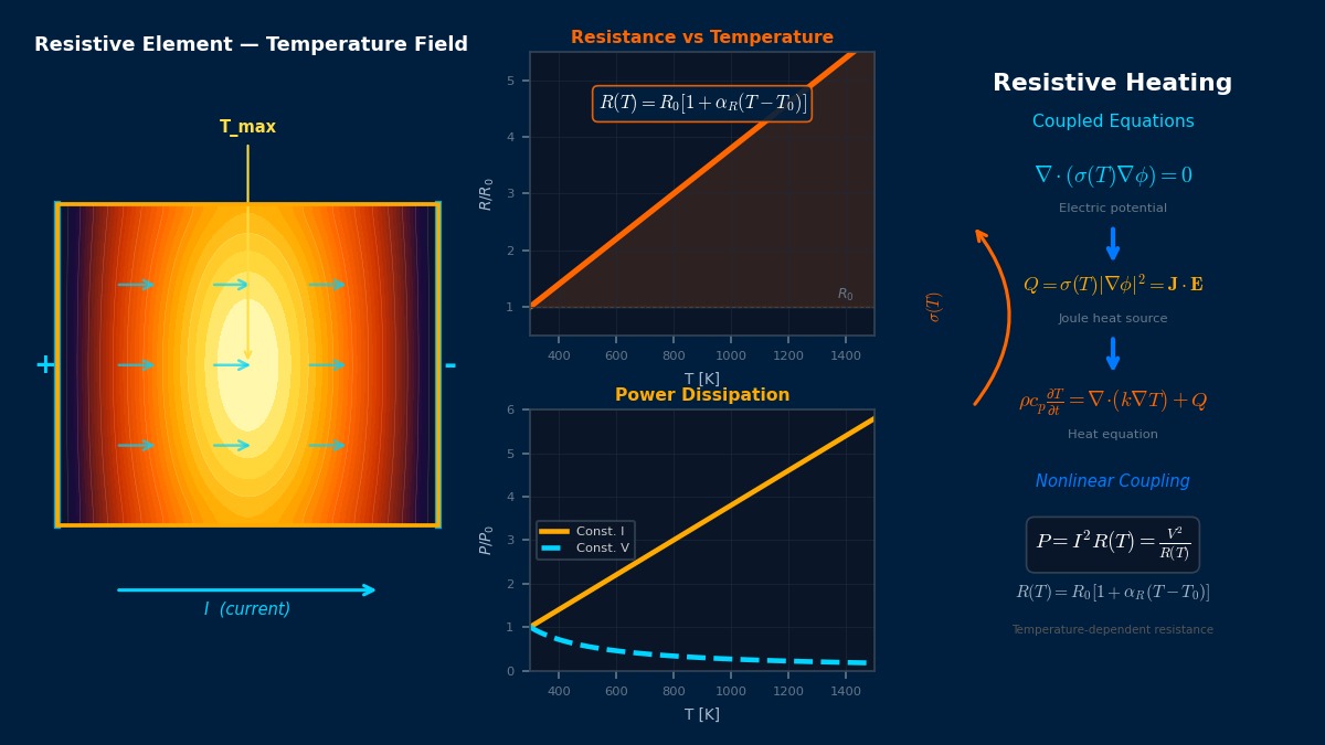
Overview
Professor! Today's topic is resistance heating analysis, right? What is it?
Theory: current becomes heat, heat changes resistance
Overview
I want to check a wire's current rating by analysis. Can I just use the room-temperature resistance?
At small currents that's roughly fine, but not where temperature rises tens of kelvin. Copper resistance rises about 0.39% per kelvin, so 100 K raises it about 1.4 times; at the same current heating is also 1.4 times, raising temperature further. Current makes heat, heat changes resistance — resolving that loop is electro-thermal coupled analysis. With weak cooling, temperature can keep climbing: thermal runaway.
Joule heat and temperature-dependent resistance
$\mathbf{J}$ is current density, $\sigma$ conductivity and $\rho$ resistivity. For copper $\rho_{20}$ = 1.72×10⁻⁸ Ω·m and $\alpha_{20}$ = 0.00393 1/K. Heater alloys such as nichrome are designed with small coefficients so resistance barely changes with temperature.
Heat balance of a wire
Balance of heat generated per length (left) and heat lost from the surface (right). $h$ is the heat transfer coefficient, $d$ diameter and $T_a$ ambient temperature. The left side grows with temperature; if heat loss can't keep pace, no balance temperature exists.
Brief high current (adiabatic)
For large currents lasting seconds or less, as in short circuits, temperature rises before heat escapes, so heat loss is ignored and only the conductor's own heat capacity counts. $\rho_m$ is density and $c$ specific heat.
Joule's measurements and the light-bulb filament
In 1841 Joule immersed wires in water, passed current and showed from the temperature rise that heat is proportional to current squared times resistance — an experiment on the road to energy conservation. The most familiar application of resistive heating is the incandescent bulb: its tungsten filament exceeds 2,000 °C in operation, with resistance over ten times its room-temperature value. Bulbs usually fail at switch-on, when the cold filament's low resistance lets nearly ten times rated current flow for an instant — temperature-dependent resistance at centre stage again.
Worked examples
Example 1: coupled or not
Steady temperature of a bare 1 mm² copper wire (1.13 mm diameter) in still 25 °C air, with a constant heat transfer coefficient of 20 W/(m²·K):
| Current | Constant resistance | Temperature-dependent (coupled) |
|---|---|---|
| 5 A | 31 ℃ | 31 ℃ |
| 10 A | 50 ℃ | 52 ℃ |
| 15 A | 81 ℃ | 96 ℃ |
| 20 A | 124 ℃ | 185 ℃ |
No difference at low current, but over 60 K at 20 A.
The larger the temperature rise, the more resistance grows. In this model (constant heat-loss coefficient), beyond about 32 A no balance exists and runaway occurs. In reality convection and radiation strengthen with temperature, so it isn't that extreme, but the tendency — uncoupled analysis is badly optimistic at high temperature — holds. With insulation rated around 90–105 °C, coupling starts to matter for the decision from about 15 A.
Example 2: short-circuit heating
| Condition (1 mm² copper) | Temperature reached (from 25 °C) |
|---|---|
| 100 A for 1 s | 81 ℃ |
| 200 A for 1 s | 334 ℃ |
| 100 A for 5 s | 457 ℃ |
Doubling current more than quadruples heating (resistance rises too). Breakers and fuses are chosen from the current–time relation so they interrupt before the wire reaches a temperature that damages insulation.
Example 3: constant current versus constant voltage
| Resistance increase | Heat at constant current | Heat at constant voltage |
|---|---|---|
| ×1.2 | ×1.20 | ×0.83 |
| ×1.4 | ×1.40 | ×0.71 |
Wiring and busbars are current-driven, so heating grows with temperature, whereas voltage-driven heaters self-stabilise as heating falls with temperature. Analyses must specify whether the source is current, voltage or controlled, or temperature predictions will err in the wrong direction.
How to approach the analysis
Procedure
- Solve current-density distribution from the conductor geometry (a current-flow analysis for DC or low frequency).
- Pass Joule heat to the thermal analysis and solve temperature.
- Update resistivity from temperature, re-solve the current field and iterate until temperature converges.
- Include contact resistance at terminals and bolted joints, where local heating concentrates.
Cautions
- Cooling conditions: heat transfer coefficients vary with temperature and orientation; include radiation; bundled wires heat each other.
- Higher frequency: AC skin effect crowds current to the surface, raising resistance above DC.
- Material limits: confirm allowable temperatures of insulation, solder and resins first and use them as criteria.
“One loose bolt started a fire”
A common cause of switchboard fires is under-tightened terminal screws. A smaller contact area raises contact resistance, generating heat there; heating oxidises the surface, raising resistance further and temperature again — local thermal runaway. The wire may be well within its rating while the terminal alone reaches hundreds of degrees. Ignoring contact resistance in analysis hides this most dangerous spot, which is why inspections use infrared cameras to find such local heating.
Common mistakes
Mistakes and fixes
| Mistake | Effect | Fix |
|---|---|---|
| Fixing resistance at room temperature | High temperatures underestimated | Iterate with temperature dependence |
| Confusing current and voltage sources | Trend reversed | Check source conditions |
| Ignoring contact resistance | Terminal overheating missed | Model contacts |
| Steady analysis of short circuits | Temperature underestimated | Adiabatic transient |
| Evaluating bundled wires singly | Temperature underestimated | Evaluate the bundle |
I'd like to compute wire and busbar heating myself.
Try the busbar sizing tool for busbar cross-sections, the Ohm's law tool for resistance and heating, and the 1D heat conduction tool for heat flow. Related heating mechanisms are covered in Joule heating, induction heating, eddy-current heating and transformer hot spots.
Related Topics
Experience the theory firsthand with the interactive simulator for this field
All Simulators