Automotive Aerodynamics Simulation
Automotive Aerodynamics: Theoretical Foundations
Overview
Professor, what is the purpose of aerodynamic simulation for automobiles?
Automotive aerodynamics has three main goals: (1) Improving fuel efficiency by reducing drag coefficient $C_D$, (2) Ensuring high-speed stability by reducing lift coefficient $C_L$, and (3) Reducing wind noise.
Aerodynamic drag is proportional to the square of velocity. It directly affects fuel consumption during high-speed driving, so even a $C_D$ improvement of 0.01 can improve fuel efficiency by about 0.3--0.5%. It also significantly impacts the range of EVs.
Governing Equations
Aerodynamic drag force on a vehicle:
Here, $A$ is the frontal projected area (approximately 2.0--2.5 m^2 for passenger cars).
Typical $C_D$ values for vehicle types:
| Vehicle Type | $C_D$ | Notes |
|---|---|---|
| Sedan (General) | 0.28--0.35 | Standard passenger car |
| Tesla Model S | 0.208 | Among the lowest for production cars as of 2024 |
| Mercedes EQS | 0.20 | World's lowest for a production car |
| SUV | 0.35--0.45 | Disadvantaged by taller height |
| Truck | 0.6--0.9 | Boxy shape |
$C_D = 0.20$ is quite low, isn't it?
An ideal streamlined shape (teardrop) has $C_D \approx 0.04$. Practical vehicle designs have constraints like cabin space and regulations, so 0.20 is an extremely excellent value for a production car.
Reynolds Number and Flow Characteristics
The Reynolds number for passenger cars, based on vehicle length, is $Re \approx 3 \times 10^6$--$10^7$. This is in the fully turbulent regime, and the influence of boundary layer transition is relatively small.
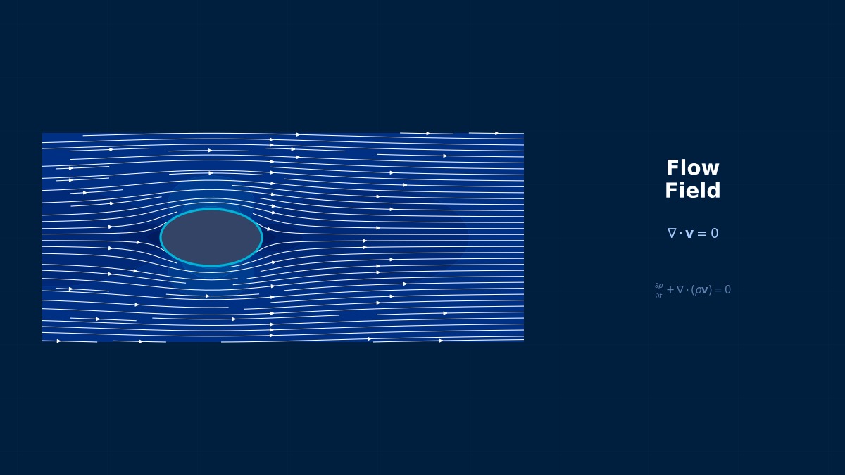
Characteristics of flow around a vehicle:
- Stagnation Point: Near the front grille
- Acceleration Region: Hood top, roof
- Separation Point: A-pillar, rear window trailing edge
- Wake: Large vortex structures (main contributor to drag)
- Underbody: Ground effect, complex flow around tires
Drag changes significantly with the rear shape, right?
Research on the Ahmed body (a standard benchmark for automotive aerodynamics) shows that the wake structure changes dramatically at rear slant angles of 25 and 35 degrees. At 25 degrees, C-pillar vortex structures form; at 35 degrees, full separation occurs, causing a discontinuous change in $C_D$.
Driving Resistance and Fuel Consumption
Breakdown of driving resistance:
| Speed | Contribution of $F_{aero}$ |
|---|---|
| 60 km/h | Approx. 30% |
| 100 km/h | Approx. 60% |
| 130 km/h | Approx. 75% |
So aerodynamics becomes dominant at highway speeds.
The Prius's Cd=0.25 and the "Mirrorless" Debate
The first-generation Prius had a Cd of 0.29, but the third generation achieved 0.25, which was top-class for production cars at the time. The development team particularly debated the side mirrors. Calculations showed that replacing mirrors with cameras could further improve Cd by 0.004–0.006. However, they gave up due to the barrier of Japanese road traffic laws at the time. Even if CFD shows "this would improve things," it's an everyday occurrence in practice that legal regulations or mass-production costs make it impossible. I wonder how the engineers felt when camera mirror systems were later legalized by law revisions.
Computational Methods for Automotive Aerodynamics
Analysis Methods
What methods are used in automotive aerodynamic CFD?
Let's organize the method options and their applications.
| Method | Cell Count | Application | Usage at OEMs |
|---|---|---|---|
| Steady RANS | 30--100 million | $C_D$/$C_L$ design evaluation | All OEMs |
| Unsteady RANS (URANS) | 50--200 million | Fluctuations around side mirrors | Many OEMs |
| DES/DDES | 100--500 million | Wake, A/C pillar vortices | Top OEMs |
| LBM (PowerFLOW, etc.) | Several hundred million voxels | Full-vehicle unsteady analysis | BMW, Ford, etc. |
| LES | 500 million--1 billion+ | Research purposes | Universities & Research Institutes |
It's well-known that BMW uses PowerFLOW, right?
BMW has been using PowerFLOW (Lattice Boltzmann Method) as a main tool for production vehicle development for over 20 years. Its strengths are easier mesh generation compared to traditional N-S solvers and good reproduction of unsteady wake flows.
Mesh Strategy
Full-vehicle mesh:
- Surface Mesh: Tri-mesh of 3--5mm on vehicle surface
- Prism Layer: $y^+ \approx 30$--100 (using wall functions) or $y^+ < 1$ (Low-Re wall treatment)
- Wheel Rotation: MRF / Sliding Mesh
- Moving Ground: Same speed as vehicle
- Radiator: Porous media model (pressure loss coefficient obtained from measurements)
- Engine Bay: Model internal flow paths (pressure loss in cooling system)
- Far-field Boundary: More than 5 times the vehicle length
So sometimes wall functions are used, and sometimes not.
In production vehicle development, wall functions ($y^+ \approx 30$--100) are often used due to computational time constraints. While absolute accuracy of $C_D$ is inferior to $y^+ < 1$, it is sufficiently practical for evaluating design change differences ($\Delta C_D$).
Rotating Wheels and Contact Patch
Wheels account for about 25--30% of total drag, making them an important element.
| Modeling Element | Effect | Notes |
|---|---|---|
| Wheel Rotation | $\Delta C_D \approx +0.015$ | Significant change with/without rotation |
| Tire Deformation | $\Delta C_D \approx +0.005$ | Influence of contact patch shape |
| Brake Cooling Duct | $\Delta C_D \approx +0.003$ | Influence of internal flow |
| Rim Design | $\Delta C_D = -0.005$--$+0.010$ | Depends on open area ratio |
Wheels alone affect $C_D$ by more than 0.02?
In recent EVs, attaching aerodynamic wheel covers to reduce $C_D$ is a trend. The Tesla Model 3's aero caps reduce $C_D$ by 0.008. CFD is indispensable for evaluating such fine $\Delta C_D$ values.
Convergence Criteria
- Residuals: Below $10^{-4}$ (for all: mass, momentum, energy)
- $C_D$ oscillation amplitude: Stable within $\pm 0.001$
- $C_L$ oscillation amplitude: Within $\pm 0.005$
- Iteration count: Typically converges in 2000--5000 iterations
Why the Ahmed Body Became the World Standard Benchmark
The "Ahmed Body," often used for verification in automotive aerodynamic CFD, is a simple box-shaped model for which Ahmed et al. published wind tunnel experimental data in 1984. With a rear slant angle of 25°, strong longitudinal vortices occur; at 35°, Cd drops sharply. Whether CFD can reproduce this "slant angle sensitivity" became a litmus test for a model's capability. Various tools like Fluent, OpenFOAM, SUPERFLOW have been verified with this case, and it has become customary for automotive aerodynamic engineers to first confirm their CFD settings with the Ahmed Body.