Aerodynamics of Racing Cars
Aerodynamics of Racing Cars: Theoretical Foundations
Overview
Teacher, the aerodynamics of racing cars are completely different from production cars, right?
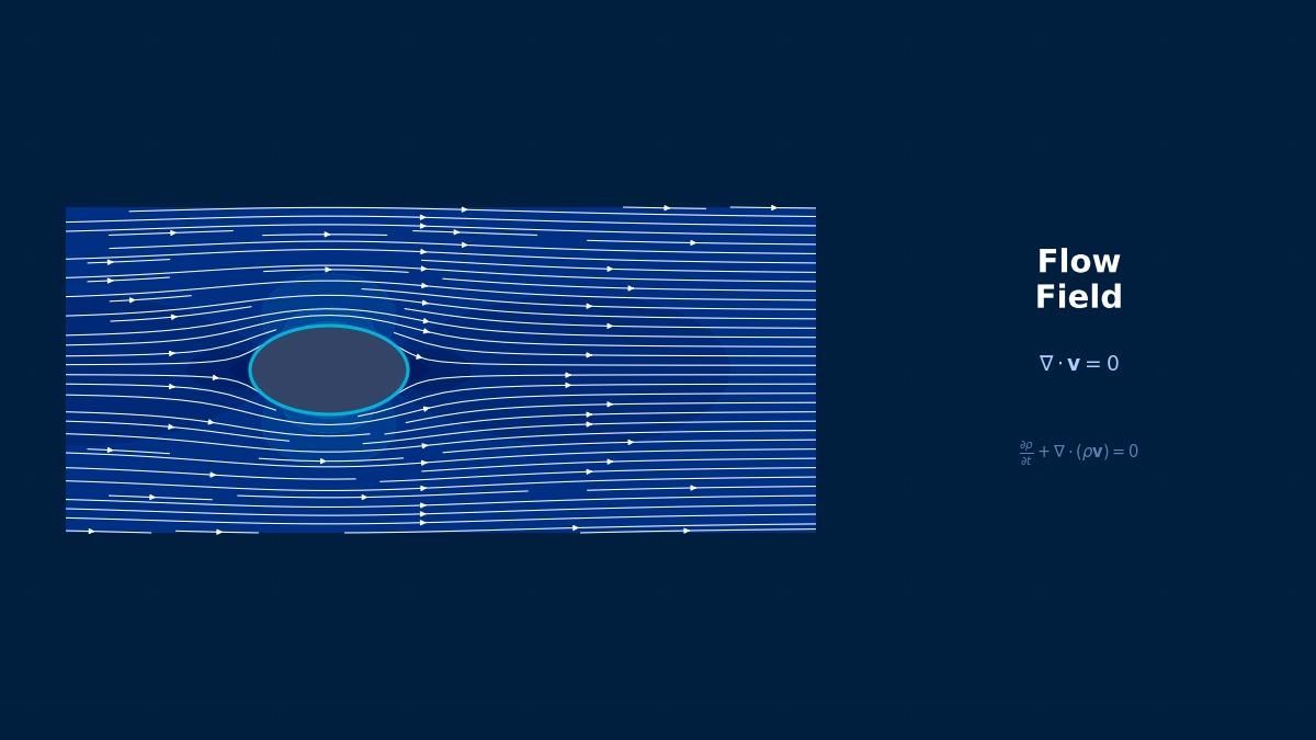
The fundamental objectives are different. For production cars, the main goal is reducing aerodynamic drag, but for racing cars, the goal is to maximize downforce (negative lift) while keeping drag within acceptable limits.
An F1 car generates about 3.5G of downforce at 300 km/h. This pressing force, significantly exceeding the car's weight, theoretically allows it to drive upside down on a ceiling.
Being able to drive on the ceiling... that's incredible force.
This downforce determines cornering speed. Since tire grip is proportional to vertical load, increasing downforce raises the cornering limit.
Governing Equations and Aerodynamic Coefficients
Downforce and drag are expressed using dimensionless coefficients.
Here $A$ is the frontal projected area. For F1 cars, $C_L \approx -3.0$--$-5.0$, $C_D \approx 0.7$--$1.2$, and $L/D \approx 3$--$5$.
So the L/D ratio is the indicator of aerodynamic efficiency for racing cars.
Correct. A higher L/D means obtaining large downforce with low drag. Floor design utilizing ground effect is key to improving L/D.
Downforce Generation Mechanisms
Let's organize the main sources of downforce.
| Element | Downforce Contribution | Main Principle |
|---|---|---|
| Front Wing | 25--30% | Bernoulli effect via inverted airfoil |
| Rear Wing | 30--35% | Inverted airfoil + multi-element flaps |
| Floor/Diffuser | 35--45% | Ground effect, Venturi effect |
| Others (Bargeboards, etc.) | 5--10% | Flow control via vortex generation |
The floor contributes the most?
Ground effect increases flow velocity in the narrow gap with the ground, creating a large low-pressure area via Bernoulli's principle. It has very high L/D because drag increase is small. Since the 2022 F1 regulations, designs actively utilize ground effect.
Reynolds Number and Flow Characteristics
The typical Reynolds number around a racing car, based on car length, is $Re \approx 10^7$.
Flow characteristics:
- Front: Bluff body flow: Stagnation point, large-scale separation
- Wing: Flow around airfoils (high angle of attack)
- Wheel: Unsteady vortices from rotating bluff body
- Diffuser: Flow in an expanding duct under adverse pressure gradient
- Wake: Interference of multiple vortex structures
The whole car is a collection of various aerodynamic phenomena, isn't it?
Why Were Ground Effect Cars Banned?
In the late 1970s, F1 teams developed "ground effect cars" that shaped the underside of the floor like a wing to generate intense downforce. Cornering G-forces exceeded 5G, and drivers raced on the verge of blacking out. In 1982, the FIA introduced flat-bottom regulations and banned them for safety reasons. When this technology was permitted again 40 years later in the 2022 regulations as a "phased return of ground effect," aerodynamic engineers reportedly cheered, "It's finally back!"
Computational Methods for Aerodynamics of Racing Cars
Analysis Method Selection
What analysis methods are used in racing car CFD?
RANS, DES/DDES, and LES are all used appropriately.
| Method | Scale | Application | Team Usage |
|---|---|---|---|
| Steady RANS | 50 million--100 million cells | Design exploration, Parametric studies | All teams |
| Unsteady RANS | 100 million--200 million cells | Unsteady aerodynamic characteristics | Top teams |
| DDES | 200 million--500 million cells | Wake interference, tire vortices | Top teams |
| LBM (PowerFLOW/XFlow) | Several hundred million voxels | Full-car unsteady analysis | Some teams |
How much computational resources do F1 teams use?
FIA regulations limit CFD usage (ATR: Aerodynamic Testing Restrictions). As of 2024, the champion team has an annual limit of 25 Teraflop-hours. This roughly corresponds to a 2000-3000 core HPC cluster running at full capacity for one year.
Mesh Strategy
The following are important for full-car mesh generation.
- Wall Prism Layers: $y^+ \approx 1$, 20--30 layers. Especially critical for wings and floor
- MRF (Moving Reference Frame): Models wheel rotation
- Ground Boundary: Moving wall condition. Moves at the same speed as the car
- Refinement Zones: Wing tips, diffuser exit, wake region
- Total Cell Count: RANS 50-100 million, DDES 200-500 million
The ground is set as a moving wall?
In actual driving, the car moves forward, but in CFD, the car is fixed and the ground is moved at the flow velocity. If you forget this and set the ground as a fixed wall, the ground boundary layer develops and ground effect is not correctly reproduced.
Turbulence Model
What turbulence models are recommended for racing car CFD?
SST k-omega is the industry standard. The SA model is also used, but SST is superior for predicting separation under adverse pressure gradients.
Detailed wing analysis:
- SST k-omega: Steady RANS. Good for predicting wing surface pressure distribution and separation location
- SST k-omega + gamma-Re_theta: When transition prediction is needed (low Re airfoils)
- DDES (SST based): Analysis of unsteady vortex structures in wing wake
Rotating Wheel Treatment
How is wheel rotation modeled?
There are three methods.
| Method | Overview | Accuracy | Cost |
|---|---|---|---|
| MRF (Frozen Rotor) | Steady calculation in rotating reference frame | Low--Medium | Low |
| Sliding Mesh | Physically rotates the rotating region | High | High |
| Overset Mesh | Overlays rotating mesh | High | Medium--High |
MRF is common in the design exploration phase with steady RANS. To accurately capture unsteady vortex structures in the tire wake, use Sliding Mesh or Overset Mesh. STAR-CCM+'s Rigid Body Motion is user-friendly.
How is tire deformation (flex) handled?
Tire deformation is typically not modeled in aerodynamic CFD. A rigid tire geometry is used from previous test data or structural simulations. Some advanced analyses use a moving contact patch based on tire load and properties.
Related Topics
Experience theory hands-on with interactive simulators in this field
All Simulators