Topology Optimization (Topology Optimization) — CAE Glossary
What is Topology Optimization
I hear "topology optimization" mentioned a lot these days. How is it different from shape optimization and size optimization?
In simple terms, size optimization decides "what thickness should the plate be," and shape optimization decides "how should the external contour curve move." But topology optimization goes much more fundamental—it decides "where should holes be punched and where should material remain." The material distribution within the design space itself becomes the design variable.
So it's possible to get shapes that humans would never think of?
Exactly. The results often come out as organic, bone-like trabecular structures. In fact, the internal structure of the human femur is a naturally optimized example of topology optimization under load. For instance, optimizing a suspension arm for a car can yield a branching, truss-like structure that achieves 30-50% weight reduction compared to traditional stamped designs—something a human designer would struggle to conceive.
SIMP Method (Density Method)
How does the SIMP method that's widely used in commercial solvers actually work?
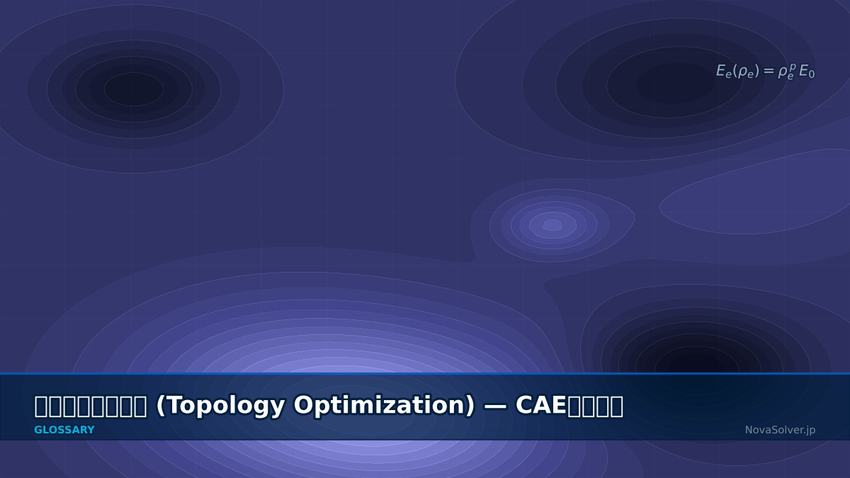
SIMP (Solid Isotropic Material with Penalization) assigns a pseudo-density variable $\rho_e$ between 0 and 1 to each finite element. The key insight is that element stiffness is penalized by a power of density:
where $E_0$ is the original material Young's modulus, and $p$ is the penalization coefficient (typically $p=3$). When $\rho_e=1$, material exists ($E_e = E_0$); when $\rho_e=0$, it's void ($E_e = 0$). The crucial point is that with $p > 1$, intermediate densities (like $\rho_e=0.5$) yield only $0.5^3 = 0.125$ of the original stiffness. This creates pressure to push solutions toward 0 or 1 rather than settling at intermediate values.
So the penalty discourages intermediate densities. But doesn't "grayscale"—intermediate density that won't disappear—still occur?
It can happen, especially with complex loading or relaxed volume constraints. The industry has several remedies:
- Density filtering — Replace each element's density with the weighted average of neighboring elements to eliminate checkerboard patterns
- Heaviside projection — Further project the filtered density toward 0 or 1 through a step-function-like transformation
- Continuation methods — Gradually increase penality coefficient $p$ during optimization (1 → 2 → 3) to start broad and narrow down to 0/1
Commercial solvers like OptiStruct, Ansys Mechanical, and TOSCA Structure handle these automatically, but understanding the underlying parameters prevents surprises.
Level-Set Method
I've heard there are other methods besides SIMP. How does the Level-Set method compare?
The Level-Set method represents structural boundaries through an implicit function $\phi(\mathbf{x})$: material exists where $\phi > 0$, void where $\phi < 0$, and the boundary is at $\phi = 0$. The optimization evolves $\phi$ via the Hamilton-Jacobi equation to move the boundary:
$V_n$ is the boundary velocity in the normal direction, determined by sensitivity analysis. The biggest difference from SIMP: boundaries are always sharp. Grayscale problems don't inherently occur, and resulting shapes are smooth and CAD-friendly.
So Level-Set sounds superior. Why is SIMP more dominant?
Level-Set has drawbacks. Standard implementations struggle with spontaneously nucleating new holes—if you start without internal voids, the optimized design may also lack them. Topological derivative techniques can address this, but add complexity. SIMP, on the other hand, simply adds density variables to existing FEM solvers, making it much easier to integrate into commercial codes. SIMP dominates with roughly 80%+ market share in industry. Level-Set remains active in research and is gaining traction with AM applications.
Compliance Minimization
What is "compliance minimization" that's frequently mentioned in topology optimization? Not regulatory compliance, right? 😅
Ha, no! In structural mechanics, compliance $C$ is a measure of structural flexibility, defined as the inner product of force and displacement:
Large compliance = flexible = low stiffness. So minimizing compliance = maximizing stiffness. The standard formulation is:
$V^*$ is the allowable volume (e.g., 40% of design space), $v_e$ is each element's volume, and $\rho_{\min}$ is a small value for numerical stability (typically $10^{-3}$).
So you can remove 60% of material and only keep 40%? That's impressive. But are there other objective functions? Sometimes we want to minimize stress, not just compliance.
Great question. Practical extensions include:
- Stress-constrained topology optimization — Ensures local stresses don't exceed allowable limits. However, adding constraints for thousands to millions of elements is computationally heavy. P-norm or KS function aggregation is standard practice.
- Eigenfrequency maximization — Increases first natural frequency, useful when vibration avoidance is critical. Common in automotive bodies and brackets.
- Multi-load-case optimization — Combines compliance across multiple loading scenarios. Real parts rarely experience just one load condition.
But compliance minimization is the gold standard starting point. It's self-adjoint, making sensitivity calculation straightforward and convergence stable.
Incorporating Manufacturing Constraints
Can topology optimization results be infeasible to manufacture? Like, for an injection-molded part, undercuts are a no-go, right?
Exactly—that's the crux of applied topology optimization. Without manufacturing constraints, you get beautiful but unfabricable shapes. Here are the main constraints:
- Minimum feature size constraint — Controlled via density filter radius $r_{\min}$. Setting $r_{\min}=3\,\text{mm}$ prevents features smaller than 3 mm
- Draft direction constraint — For injection molding and die casting. Enforces monotonicity of density distribution along a specified unmold direction to eliminate undercuts
- Symmetry constraint — Enforces mirror or rotational symmetry, reducing optimization problem size and manufacturing complexity
- Maximum feature size constraint — Prevents overly large solid regions to avoid shrinkage cavities in casting
- Extrusion constraint — For sheet metal stamping or aluminum extrusions. Forces cross-section uniformity along one direction
That's a lot of constraints! Do they change the optimized result dramatically?
Dramatically. An unconstrained suspension bracket might yield a 3D branching structure. Add draft direction constraints, and it transforms into manufacturable ribs. Stiffness might drop 10-20%, but now it's producible. The real value is quantifying the trade-off: "Does the manufacturing cost savings of a simpler process justify the extra weight?" That insight comes from comparing unconstrained vs. constrained results.
Integration with Additive Manufacturing (AM)
I heard you can now 3D print the exact topology optimization result without modification. Is everything really possible with AM?
"AM enables complete freedom" is half right, half wrong. Yes, you lose draft direction and undercut constraints. But AM has its own constraints:
- Overhang constraint — Powder-bed methods (SLM/SLS) require support material for overhangs steeper than ~45° from build direction. For support-free printing, include overhang angle limits in optimization.
- Minimum wall thickness — Depends on laser spot size and powder particle size. Metal AM typically requires 0.3-0.5 mm minimum.
- Residual stress and warping — Thermal history during layer-by-layer buildup causes residual stresses. Thin walls or sharp corners risk cracking.
- Powder removal — Internal closed voids trap unfused powder. Must include drain holes or use lattice structures for infill.
How do you actually enforce overhang constraints in optimization? The shape must change quite a bit.
A typical approach constrains element densities so they're always greater than or equal to elements below them in the build direction (e.g., +Z). This is implemented filter-like and results in "mushroom-shaped" overhangs disappearing, replaced by inverted-cone or tree-like self-supporting forms. OptiStruct, nTopology, and Siemens NX TOPO now offer AM constraints in their GUIs. GE Aviation's Fuel Nozzle Tip is a famous example: consolidated 20 welded parts into one AM part, achieving 25% weight reduction and 5× durability increase.
Practical Workflow and Considerations
What's the typical workflow for actually using topology optimization? Just feed everything to the solver?
Not quite. Here's the industrial standard:
- Define design space — Separate optimizable regions (Design Space) from fixed regions (Non-Design Space: bolt holes, mating faces). This is the most critical step—too narrow limits freedom; too broad produces unrealistic shapes.
- Set loads and constraints — Define all use cases as load steps. Missing cases means "optimal for ignored loading" results.
- Choose objective and constraints — E.g., minimize compliance + 40% volume constraint.
- Add manufacturing constraints — Draft direction, minimum features, symmetry, etc.
- Run optimization — Typically 50-200 iterations; convergence judged by compliance change rate.
- Extract and rebuild in CAD — Extract iso-surface (typically at $\rho=0.3$), smooth, add fillets, reconstruct as CAD geometry.
- Verify with full FEA — Run standard FEM analysis on the final CAD shape to confirm stresses and deflections.
So you reconstruct in CAD and reverify? That seems redundant.
It's essential, not redundant, for three reasons. First, optimization typically uses coarse meshes (for speed), so stress accuracy is limited. Second, CAD reconstruction and fillets change geometry. Third, optimization assumes linear-static behavior, but real parts often need nonlinear analysis (large deformation, contact, fatigue). The optimization phase is concept generation; final validation is separate.
How do you choose mesh size for the optimization? Finer is always better?
Finer meshes improve resolution but cost scales with element count. Since topology optimization re-solves FEM every iteration, 1M elements × 200 iterations = ~200M solves. A practical rule: the minimum feature constraint $r_{\min}$ should span at least 3-4 elements. For example, if $r_{\min}=5\,\text{mm}$, use element size around 1.2-1.7 mm. Start coarse to explore trends, then refine for final runs.
Related Terms
What key terminology should I know about in the topology optimization space?
Accurate understanding of CAE terminology is the foundation for effective team communication. — Project NovaSolver supports learning for practitioners.
Tell us about the challenges you face with topology optimization in your work
Project NovaSolver aims to solve real problems that CAE engineers encounter daily—setup complexity, computational cost, result interpretation. Your practical experience drives better tools.
Contact Us (Coming Soon)Related Topics
details
error