J-Integral (Elastic-Plastic Fracture Mechanics)
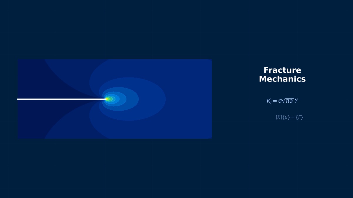
J-Integral (Elastic-Plastic Fracture Mechanics): Theoretical Foundations
What is the J-Integral?
Professor, what is the J-integral?
The J-integral (Rice, 1968) is a parameter representing the energy release rate at the crack tip. It is a concept that extends the stress intensity factor (SIF) $K$ from linear elastic fracture mechanics to elastic-plastic conditions.
$\Gamma$ is any path surrounding the crack tip. $W$ is the strain energy density, $\mathbf{T}$ is the traction vector.
Path independent! So "the value is the same no matter where the integration path is taken".
Path independence depends on material, loading, body forces and thermal strains. For elastic-plastic analysis, proportional monotonic loading is important; unloading in the crack-tip plastic zone generally requires reassessing J validity. Also check contour and mesh convergence.
Relationship between $J$ and $K$
For linear elasticity:
$E' = E$ (Plane stress), $E' = E/(1-\nu^2)$ (Plane strain). $J$ is proportional to the square of $K$.
Fracture Condition
$J_{Ic}$ is the critical J-integral value (material property). The test method is specified in ASTM E1820.
Summary
Key Points:
- $J$ = Energy release rate at the crack tip — Applicable to elastic-plastic conditions
- Path independent — Path independence depends on material, loading and other assumptions
- $J = K^2/E'$ — Relationship with linear elasticity
- Fracture when $J \geq J_{Ic}$ — $J_{Ic}$ measured per ASTM E1820
- FEM *CONTOUR INTEGRAL — Automatically calculates J at the crack tip
Rice Changed the World with a 9-Page Paper
The J-integral was proposed by James Rice (Harvard University) in a 9-page paper published in the JAppl Mech journal in 1968. Path independence holds under specific material, loading, body-force and thermal-strain assumptions and can support elastic-plastic fracture assessment when those assumptions apply. This discovery enabled the extension of fracture mechanics to elastic-plastic regimes, and Rice received the Timoshenko Award in 1983.
Computational Methods for J-Integral (Elastic-Plastic Fracture Mechanics)
J-Integral in FEM
*CONTOUR INTEGRAL, CONTOURS=5, TYPE=J
crack_tip_node, direction_vector
Calculates J for 5 contours. The value should converge as the contours move away from the crack tip.
What if the values don't converge across the 5 contours?
The mesh is too coarse or the plastic zone is large. Refine the mesh or increase the number of contours. Convergence is OK if the values from the outer 3-4 contours are nearly identical.
Crack Tip Meshing
Place a concentrated mesh (Spider web mesh) at the crack tip. Elements are arranged radially from a central point (the crack tip).
- Recommended: 2nd-order elements (C3D20R) — Accurately captures the singularity at the crack tip.
- Quarter-Point elements — Move the midside node to the 1/4 point at the crack tip. Models the $1/\sqrt{r}$ singular field.
Summary
J-Integral Calculation in FEM: Virtual Crack Extension Method
The virtual crack extension method (Domain integral method) is superior in both accuracy and efficiency for J-integral calculation in FEM. It integrates only over a region 3-5 elements away from the crack tip and does not require FEM singular elements (collapsed quarter-point elements). ANSYS's FRACTURE TB command internally uses this method and automatically outputs the average value from paths 1-10, making convergence checks easy.
J-Integral (Elastic-Plastic Fracture Mechanics) in Practice
J-Integral in Practice
Used in pressure vessel crack assessment (API 579 FFS-1), pipeline defect assessment, and nuclear fracture mechanics evaluation (R6 method).
ASTM E1820 Test
Test for J-R curve (J vs. crack extension $\Delta a$). Conducted using CT (Compact Tension) specimens. Obtain $J_{Ic}$ (critical value for crack initiation) and the J-R curve.
Practical Checklist
Elastic-Plastic Fracture Assessment of Pressure Vessel Nozzle Junctions
ASME Sec.XI Code uses the J-integral for crack assessment at pressure vessel nozzle fillet regions. Using the J-R curve (J vs Δa) of SA-508 Cl.3 steel for nuclear-grade piping, the condition where an initial crack transitions to unstable growth (Ji = stable growth initiation point) is calculated. For considering 60-year extended operation, analysis is required to prove that safety margins exist even if the post-irradiation embrittlement JIc is conservatively reduced by 50%.