Stress Intensity Factor (SIF) and Fracture Mode
Stress Intensity Factor (SIF) and Fracture Mode: Theoretical Foundations
Stress Intensity Factor (SIF)
Professor, what is the Stress Intensity Factor $K$?
$K$ (Stress Intensity Factor) is a parameter representing the strength of the stress field at the crack tip. It is a fundamental quantity in Linear Elastic Fracture Mechanics (LEFM).
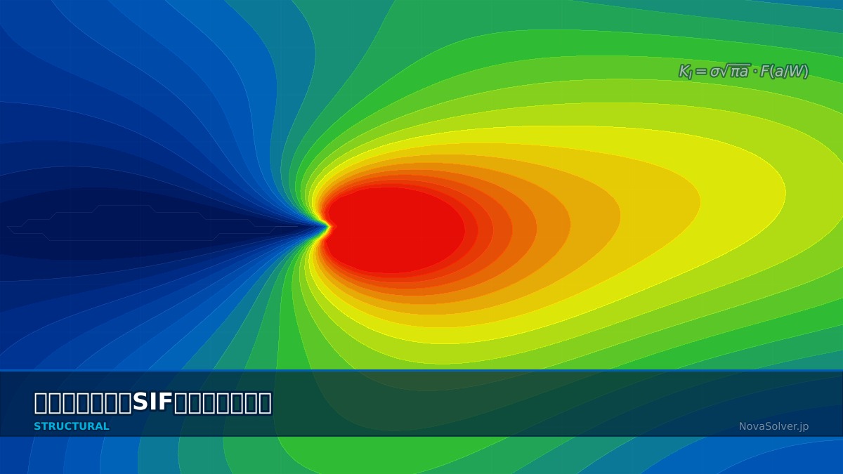
$$ K_I = \sigma \sqrt{\pi a} \cdot F(a/W) $$
Professor, what is the Stress Intensity Factor $K$?
$K$ (Stress Intensity Factor) is a parameter representing the strength of the stress field at the crack tip. It is a fundamental quantity in Linear Elastic Fracture Mechanics (LEFM).
$\sigma$: remote stress, $a$: crack length, $F$: shape correction factor.
Three Fracture Modes
| Mode | Displacement | Typical Loading |
|---|---|---|
| Mode I (Opening) | Crack faces separate | Tension |
| Mode II (In-plane shear) | Crack faces slide in-plane | Shear |
| Mode III (Out-of-plane shear) | Crack faces slide out-of-plane | Torsion |
Is Mode I the most common?
The majority of engineering crack problems are dominated by Mode I. Fracture occurs when $K_I \geq K_{IC}$ (plane strain fracture toughness).
Summary
How Irwin Developed Linear Fracture Mechanics
The concept of the stress intensity factor KI was proposed by Irwin (U.S. Naval Research Laboratory) in 1957. He integrated Inglis's (1913) elliptical notch stress analysis and Griffith's (1921) energy theory, successfully describing the strength of the crack tip stress field with a single parameter "K". The classification into three modes (I, II, III) is also his contribution, forming the basis of all current fracture mechanics standards.
Computational Methods for Stress Intensity Factor (SIF) and Fracture Mode
SIF in FEM
```
*CONTOUR INTEGRAL, CONTOURS=5, TYPE=K FACTORS
crack_tip, direction
```
Outputs $K_I, K_{II}, K_{III}$ simultaneously. Relationship with J-integral: $J = (K_I^2 + K_{II}^2)/E' + K_{III}^2/(2G)$
Quarter-Point Elements
Represents the $1/\sqrt{r}$ singular field at the crack tip. Moves the mid-side node of quadratic elements to the 1/4 position.
Summary
Conversion from J-integral to K
For elastic bodies, the relationship J=KI²/E' (with E'=E/(1−ν²) for plane strain) holds, allowing KIc to be back-calculated from FEM J-integral results. In 3D FEM, K varies through the thickness, so the average value at the surface and center is taken as the representative value. For separating stress intensity factor modes (KI, KII, KIII), the Virtual Crack Closure Technique (VCCT) is computationally efficient.
Stress Intensity Factor (SIF) and Fracture Mode in Practice
SIF in Practice
Used in crack assessment for pressure vessels, defect evaluation for piping, and damage tolerance design for aircraft.
Practical Checklist
SIF Evaluation for Oblique Cracks in Pipe Elbows
Fatigue cracks in pipe elbow sections often propagate in a mixed-mode state combining Mode I and II. In steam pipe inspection evaluation, the equivalent SIF Keq=(KI²+KII²+KIII²/(1-ν))^0.5 for obliquely oriented cracks detected by ultrasonic testing is commonly used for assessment. API 579 standardizes this calculation formula, with repair required when the KIc/Keq ratio is less than 1.0.
Stress Intensity Factor (SIF) and Fracture Mode: Software & Solver Comparison
SIF Tools
FRANC3D's Dedicated Crack Modeling Features
FRANC3D (Fracture ANalysis Code 3D) is a crack propagation analysis software originating from Cornell University, specializing in automatic SIF calculation and crack growth simulation. It partially remeshes existing FEM models to embed cracks and automates crack surface remeshing. FRANC3D was used in FAA-certified fatigue analysis of PW4000 engine fan blades.
Advanced Technology
Advanced SIF
Related Topics
Experience the theory firsthand with the interactive simulator for this field
All Simulators