Plane Stress Problem
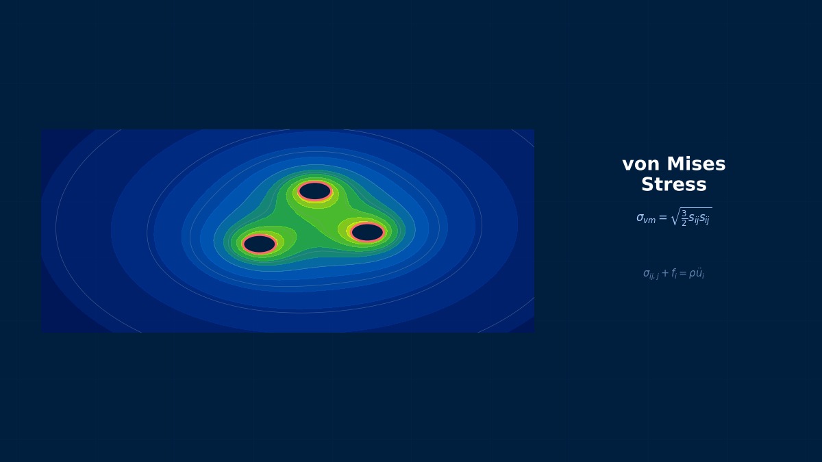
Plane Stress Problem: Theoretical Foundations
What is Plane Stress?
Professor, does "plane stress" mean reducing a 3D problem to 2D?
Yes. Solving a 3D elastic body results in a vast number of degrees of freedom. However, for thin plate-like structures subjected only to in-plane loads, the stress components in the thickness direction can be considered zero. This is the plane stress assumption.
What kind of structures fit this assumption?
Structures where the thickness is sufficiently thin compared to the in-plane dimensions. Specifically:
- Thin plates subjected to in-plane loads (tension, compression, shear)
- Analysis of brackets and sheet metal parts
- Thin walls of dams under water pressure
Conversely, when can plane stress not be used?
When there is constraint in the thickness direction. For example, thick walls of dams or cross-sections of long tunnels. In such cases, the plane strain assumption (strain in the thickness direction is zero) is used. Plane stress and plane strain are similar but distinct; confusing them leads to large errors.
Governing Equations
Please tell me the governing equations for plane stress.
2D force equilibrium equations:
Compatibility condition (strain compatibility):
What about the constitutive law (Hooke's law)?
Hooke's law for plane stress (matrix form):
$E/(1-\nu^2)$ is larger than the usual $E$, right? Because lateral deformation is constrained by the Poisson effect, the effective stiffness increases.
Good point. However, in plane stress, deformation in the lateral direction ($z$ direction) is free. $E/(1-\nu^2)$ appears because the two stress components are coupled, which has a slightly different meaning from the 3D $E$.
Important point: In plane stress, $\sigma_{zz} = 0$, but $\varepsilon_{zz} \neq 0$:
Strain occurs in the thickness direction. When the plate is stretched in-plane, it becomes thinner — this is the Poisson effect.
Plane Stress vs. Plane Strain
Please explain the difference from plane strain in more detail.
| Characteristic | Plane Stress | Plane Strain |
|---|---|---|
| Assumption | $\sigma_{zz} = 0$ | $\varepsilon_{zz} = 0$ |
| Applicable Object | Thin plates (thickness << in-plane dimensions) | Long structures (depth >> cross-sectional dimensions) |
| Deformation in $z$ direction | Exists ($\varepsilon_{zz} \neq 0$) | None |
| Stress in $z$ direction | None | Exists ($\sigma_{zz} = \nu(\sigma_x + \sigma_y)$) |
| Effective Stiffness | $E/(1-\nu^2)$ | $E(1-\nu)/((1+\nu)(1-2\nu))$ |
| Typical Example | Sheet metal bracket | Dam cross-section, long tunnel |
The effective stiffness of plane strain is larger than that of plane stress... meaning deformation is smaller under the same load.
Yes. Because deformation in the $z$ direction is completely constrained, the stiffness increases due to the 3D constraint effect. This difference is about 10% for $\nu = 0.3$. It may seem small, but it's a non-negligible difference in stress evaluation.
Airy Stress Function
I heard there is a solution method using a "stress function" for plane problems.
Using the Airy stress function $\phi(x,y)$, the equilibrium equations and compatibility condition can be combined into a single equation:
Solving this biharmonic equation, the stress components are:
So the stresses automatically satisfy equilibrium. Convenient!
Classical elasticity problems (infinite plate with a hole, wedge, half-plane contact problem) can be solved with the Airy function. The Kirsch problem (stress concentration around a circular hole in an infinite plate) is also a solution using the Airy function. It's very useful as a verification problem for FEM.
Summary
Let me organize the theory of plane stress.
Key points:
- Assumption of $\sigma_{zz} = 0$ — Applied to in-plane problems of thin plates
- Distinction from plane strain is crucial — Using the wrong assumption leads to errors of 10% or more
- Constitutive law includes $E/(1-\nu^2)$ — 2D coupling effect
- $\varepsilon_{zz} \neq 0$ — Strain exists in the thickness direction
- Classical problems can be solved with the Airy function — Useful for FEM verification
To "correctly" reduce a 3D problem to 2D, understanding the physics is essential, isn't it?
Exactly. 2D elements can dramatically reduce computational cost, but the prerequisite is to correctly judge when the assumption holds. If in doubt, solve it in 3D and compare with the 2D results.
Theoretical Basis of the Plane Stress Assumption
The plane stress assumption (σz=τyz=τxz=0) is applied to thin plates where "the thickness is sufficiently small compared to the in-plane dimensions." Kirchhoff organized the framework for separating bending and extension problems of plates in 1909, which became the analytical foundation for subsequent thin plate and membrane problems. For parts like aircraft wing spar webs and automotive door panels with thicknesses around 1-3mm, 2D plane stress models often agree with 3D shell analyses within an error margin of 1%.
Numerical Solution Methods and Implementation
Plane Stress Analysis by FEM
When solving plane stress problems with FEM, what kind of elements are used?
2D plane stress elements. Each node has 2 degrees of freedom ($u_x, u_y$), requiring about 1/3 the DOF of 3D solid elements.
Typical Element Types
| Element | Number of Nodes | Shape Function | Accuracy | Application |
|---|---|---|---|---|
| 3-node triangle (CST) | 3 | Linear | Low (constant strain) | Filling for automatic meshing |
| 6-node triangle (LST) | 6 | Quadratic | High | Automatic meshing for complex shapes |
| 4-node quadrilateral (Q4) | 4 | Bilinear | Medium | Regular mesh |
| 8-node quadrilateral (Q8) | 8 | Quadratic | High | Standard for precise analysis |
CST (Constant Strain Triangle) has constant strain within the element, as the name suggests... so it can't represent stress gradients, right?
Exactly. CST has significantly low accuracy in areas with large stress gradients like stress concentration zones. It can only be used for educational purposes or rough screening. In practice, quadratic elements (6-node triangle or 8-node quadrilateral) are standard.
Influence of Integration Scheme
When evaluating stiffness matrices with numerical integration, does the choice of quadrature rule matter?
Yes. Full integration and reduced integration give different results. For Q8 elements, the standard choice is 3×3 Gaussian quadrature (full integration), while some solvers use 2×2 (reduced integration) for computational efficiency.
Is there a "correct" choice?
Full integration (3×3) is theoretically more accurate, but it increases computational cost. Reduced integration (2×2) is faster but can introduce hourglass modes (artificial deformation patterns). Most production solvers use full integration by default for plane stress, unless explicitly tuned for speed.
Summary
So for reliable plane stress analysis by FEM, I should use quadratic elements and full integration?
Correct. Additionally, use an appropriate mesh density near stress concentration zones, verify boundary conditions match the intended model, and compare results with analytical solutions when possible. Plane stress is conceptually simple, but robust implementation requires careful attention to discretization.
Practical CAE Quality Notes for Plane Stress Problem
Plane Stress Problem should be treated as an engineering model, not as an isolated formula. In structural analysis, reliable results come from a clear chain of assumptions: governing physics, material data, boundary conditions, numerical discretization, solver settings, and post-processing criteria. Before using this note in a design review, identify which quantities are prescribed, which are solved, and which are only diagnostic indicators.
Model Setup Checklist
- Define the scope: decide whether Plane Stress Problem is being used for screening, detailed design, failure investigation, or verification of another simulation.
- Check dimensions and units: keep SI units internally and document every conversion applied to loads, geometry, material constants, and time or frequency scales.
- State assumptions explicitly: record linearity, steady-state or transient behavior, small-deformation limits, continuum assumptions, and any symmetry or ideal boundary conditions.
- Compare with a baseline: use a hand calculation, limiting case, mesh refinement trend, or independent solver result before accepting the final value.
Validation Signals
| Review Item | What to Verify | Typical Warning Sign |
|---|---|---|
| Inputs | Geometry, material data, loads, and constraints match the intended structural analysis problem. | Correct-looking plots with unrealistic magnitudes or units. |
| Numerics | Mesh, time step, convergence tolerance, and solver options are adequate for Plane Stress. | Large changes after small mesh or tolerance adjustments. |
| Physics | The selected theory remains valid in the expected stress, temperature, velocity, or frequency range. | Results are used outside the assumptions stated in the model. |
For production use, keep the model file, input table, result plots, and review comments together. This makes Plane Stress Problem traceable and prevents the page from being used as a black-box answer without engineering judgment.