Vascular Stent Deployment FSI
Overview
Professor, why is FSI necessary for simulating stent deployment in blood vessels?
Vascular Stent Deployment FSI: Theoretical Foundations
A stent is a medical device that expands a metal mesh structure inside a blood vessel to widen a narrowed vessel. The blood flow pattern after stent deployment strongly depends on the stent shape and vessel wall deformation, and is directly linked to the risk of restenosis (neointimal hyperplasia). It is known that restenosis is more likely to occur in areas with low WSS (Wall Shear Stress), so it's important to accurately predict the blood flow field and wall stress using FSI.
What types of stents are there?
There are three main types. Balloon-expandable stents (BES: coronary artery stents), self-expanding stents (SES: Nitinol alloy, for carotid/peripheral use), and drug-eluting stents (DES: coated with restenosis-inhibiting drugs). Their mechanical behaviors differ, so the structural models also change.
Governing Equations
What system of equations is solved for stent deployment FSI?
It's a coupled problem of three structures (stent, balloon, vessel wall) and blood flow.
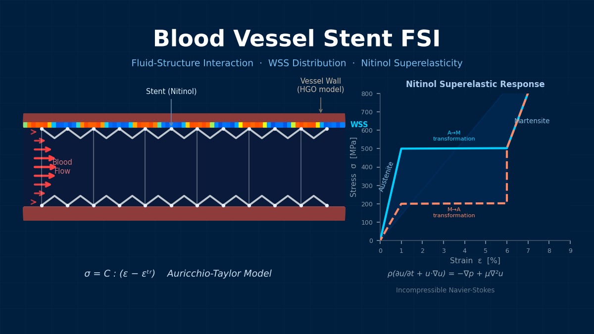
The stent is modeled with SUS316L or Nitinol (Hyperelasticity). The Auricchio-Taylor model is standard for Nitinol's hyperelasticity.
The transformation strain $\boldsymbol{\varepsilon}^{tr}$ occurs during austenite-martensite phase transformation.
The vessel wall uses the Holzapfel-Gasser-Ogden model, and blood flow uses the incompressible Navier-Stokes equations. If plaque is present, a linear elastic or plastic model is used to represent the hard layer.
How is the balloon modeled?
The balloon is a polymer thin film (e.g., polyamide) modeled with membrane elements. Internal pressure is increased stepwise to expand the stent from its crimped diameter to the target diameter. Sometimes the folded shape of the balloon is also reproduced, but it's a trade-off with computational cost.
Nitinol—How "Shape Memory" Sparked a Stent Revolution
Nitinol (Ni-Ti alloy), widely used in modern vascular stents, possesses two characteristics: shape memory effect and superelasticity. It transforms to the austenite phase near body temperature (37°C), allowing a stent inserted in a contracted state to expand naturally inside the vessel. To handle Nitinol in FSI theory, a hyperelastic constitutive law (such as the Brinson rule) is required, not the usual linear elastic model. Implementing this material model is one of the biggest factors raising the difficulty level of stent FSI analysis.
Computational Methods for Vascular Stent Deployment FSI
It's usually divided into two stages.
Stage 1: Stent Deployment (Structure Only)
1. Stent crimping (diameter reduction)
2. Expansion via balloon pressurization
3. Recoil (Springback) after balloon deflation
Stage 2: Post-Deployment FSI
1. Set the deformed shape after deployment as the initial condition
2. Import residual stresses
3. Execute FSI analysis for pulsatile blood flow
Importing residual stresses is important, I see.
Significant residual stresses exist in the stent after deployment; ignoring them drastically reduces the prediction accuracy of wall stress. Use Abaqus's *IMPORT function or Ansys's ICTRL/RESUME command to carry over the stress field from the previous analysis.
Contact Algorithm
How is contact between the stent and vessel wall handled?
There are three contact pairs: stent-balloon, stent-vessel wall, balloon-vessel wall.
| Contact Pair | Method | Friction Coefficient |
|---|---|---|
| Stent-Balloon | Surface-to-surface contact | 0.05–0.1 |
| Stent-Vessel Wall | Surface-to-surface contact | 0.1–0.2 |
| Stent-Plaque | Surface-to-surface contact | 0.2–0.3 |
In Abaqus, *CONTACT PAIR or General Contact is used; in LS-DYNA, *CONTACT_AUTOMATIC_SURFACE_TO_SURFACE is used. The Augmented Lagrangian method can suppress penetration better than the penalty method.
Mesh Strategy
Meshing the thin stent struts seems challenging.
Divide the strut cross-section (typically 80–120μm × 80–120μm) with hexahedral elements, at least 3×3. The entire stent becomes 500k–2M elements.
Locally refine the vessel wall near stent struts, using element sizes below 1/3 of the strut width. The fluid mesh needs elements placed even in the gaps between struts, often resulting in 1M–5M elements total.
With that scale, how long is the computation time?
Deployment analysis (quasi-static) typically takes 8–24 hours; FSI (several heartbeats) takes 24–72 hours. This is an estimate assuming implicit method parallel computation with 16–32 cores.
Two-Step Analysis of Stent Deployment—Solving Folding and Deployment Separately
FSI analysis of vascular stent deployment is typically performed in two steps: "structural analysis of the folding process" → "FSI analysis of deployment inside the vessel." The key point is carrying over the residual stresses generated during folding as initial conditions for the deployment analysis. If this is omitted and analysis starts from the deployed stent shape, the actual deployment force and load on the vessel can be underestimated by 20–30%. This two-step method is also increasingly required in medical device regulatory submission documents.
Vascular Stent Deployment FSI in Practice
1. Stent Shape Creation: Create the strut pattern from CAD in the deployed shape, then wrap it into a cylinder.
2. Vessel Shape Acquisition: Obtain patient-specific shape from CT/MRI, or use an ideal shape (straight tube + stenosis).
3. Material Definition: Stent (SUS316L: Elasto-Plastic / Nitinol: Auricchio hyperelasticity), Vessel wall (Holzapfel-Gasser-Ogden), Plaque (Elasto-Plastic)
4. Crimp ~ Deployment Analysis: Abaqus/Explicit or Abaqus/Standard
5. FSI Analysis of Deployed Shape: Ansys System Coupling or Abaqus co-simulation
6. Postprocessing: Stent von Mises stress (fatigue evaluation), WSS, OSI (restenosis risk evaluation)
Do you also do fatigue evaluation?
The FDA (U.S. Food and Drug Administration) mandates fatigue life evaluation for stents. Fatigue durability for 400 million cycles (equivalent to 10 years) is required. Plot mean stress and alternating stress on a Goodman diagram and confirm they are below the fatigue limit.
A safety factor SF = 2 or more is a common standard.
Common Pitfalls
Where are the tricky points in practice?
| Problem | Cause | Countermeasure |
|---|---|---|
| Stent not adhering to vessel wall | Overestimation of recoil | Set balloon overexpansion ratio (10–20%) |
| Strut fracture judgment | Mesh-dependent stress concentration | Use submodel method for local refinement |
| Unrealistic dog-boning | Balloon pressurization sequence | Stepwise division with center-first pressurization |
| WSS distribution asymmetric left-right | Influence of vessel curvature, bifurcation | Sufficient inlet development length |
What is dog-boning?
A phenomenon in balloon-expandable stents where the ends expand first and the center expands later. It causes excessive stress on the vessel wall at the stent ends, leading to restenosis. It is controlled by balloon compliance and stent cell design.