Wind Load-Structure Coupled Analysis
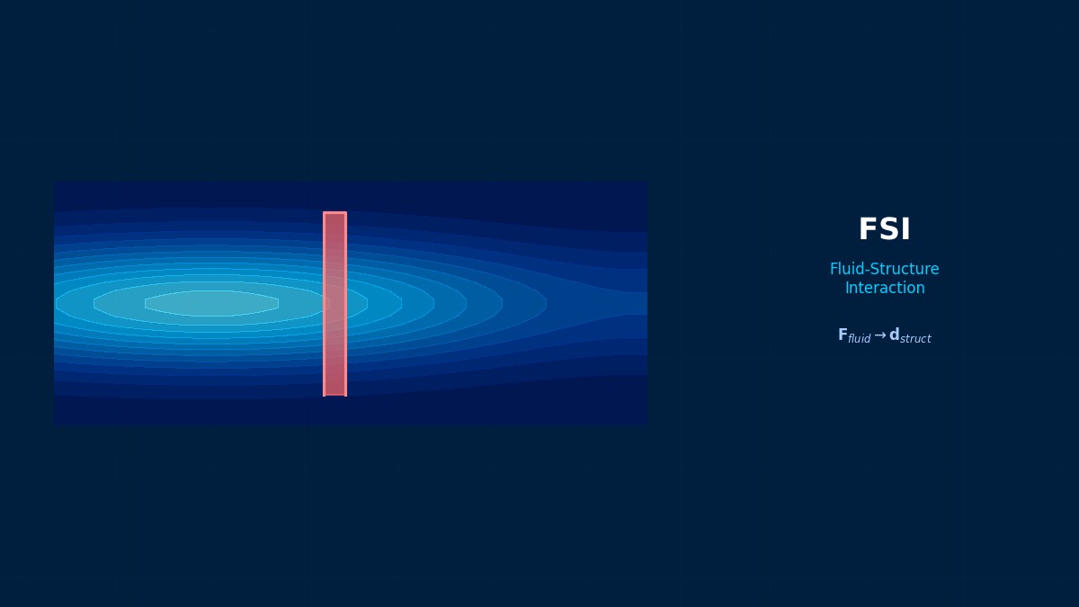
Theory: wind force and wind-induced oscillation
Overview
I'm checking a factory chimney for wind. Is it enough to check strength at typhoon wind speed?
You need two views. One is the force of strong wind pushing on it, which grows with the square of speed — check that at typhoon speed. The other is vortex-induced vibration: wind sheds vortices alternately behind the chimney, and if their frequency matches the chimney's natural frequency it oscillates strongly. That often happens at everyday wind speeds. Treat strength and oscillation as separate checks and do both.
Wind speed versus height
$V_{10}$ is the reference wind speed at 10 m and $\alpha$ the power-law exponent set by terrain roughness (about 0.1 over sea or open plains, 0.15 in suburbs, 0.25–0.3 in cities). $q$ is velocity pressure. Ground friction slows the wind, so it is stronger higher up.
Drag and base reactions
$C_d$ is the drag coefficient and $D$ the exposed width. Higher up the pressure is larger and the lever arm longer, so upper-level wind governs the base moment. Real designs add a gust factor for turbulent fluctuations.
Vortex-induced vibration speed
$St$ is the Strouhal number (about 0.2 for cylinders) and $f_n$ the structural natural frequency. Shedding frequency rises in proportion to wind speed, resonating at the critical speed $V_{cr}$. Once matched, shedding locks onto the structural motion, so resonance persists over a band of speeds (lock-in).
Tacoma Narrows and chimney strakes
In 1940 the Tacoma Narrows Bridge in the US twisted violently and collapsed in a wind of only about 19 m/s. The cause is thought to have been flutter — torsional motion drawing ever more energy from the wind — rather than vortex shedding, but it showed the world that wind can destroy a structure without a storm. Slender steel chimneys sometimes carry helical strakes on the outside, which disrupt vortices so they aren't shed in unison along the height, suppressing vortex-induced vibration.
Worked example: a 40 m chimney
Example 1: terrain roughness and base reactions
Illustrative conditions: 40 m tall, 2 m diameter cylinder, drag coefficient 0.7, air density 1.225 kg/m³ (gust factor not included).
| Exponent α | V₁₀ | Top wind speed | Top pressure | Base shear | Base moment |
|---|---|---|---|---|---|
| 0.10 | 30 m/s | 34.5 m/s | 727 Pa | 33.9 kN | 741 kN·m |
| 0.15 | 30 m/s | 36.9 m/s | 836 Pa | 36.0 kN | 814 kN·m |
| 0.25 | 30 m/s | 42.4 m/s | 1,103 Pa | 41.2 kN | 988 kN·m |
| Uniform | 30 m/s | 30 m/s | 551 Pa | 30.9 kN | 617 kN·m |
Same reference speed, yet the moment is 30% larger in the city.
Strictly, rough terrain usually also lowers the 10 m reference speed itself, so comparing at the same reference speed isn't quite fair. The key point is that ignoring the increase with height and using a uniform speed underestimates base moment by 20–40%. And because speed enters squared, raising design speed from 25 to 30 m/s multiplies force by 1.44. Choosing the reference speed and profile for the site and terrain according to the design code is the starting point.
Example 2: wind speed for vortex-induced vibration
| Chimney natural frequency | Lock-in wind speed (D = 2 m, St = 0.2) |
|---|---|
| 0.5 Hz | 5 m/s |
| 1.0 Hz | 10 m/s |
| 2.0 Hz | 20 m/s |
A chimney with a 1 Hz natural frequency resonates at an everyday 10 m/s wind. Oscillation amplitude depends on structural damping and mass (combined as the Scruton number), so light, lightly damped steel chimneys move most. Remedies are shifting the natural frequency, adding damping (dampers) or fitting strakes to break up vortex coherence. Because the motion repeats, fatigue is often more critical than strength.
How to approach the analysis
Procedure
- Take reference speed, terrain roughness and gust factor from the design code and check strength under static wind load.
- Find natural frequencies and modes and check whether vortex lock-in speeds fall within common wind speeds.
- If needed, solve the surrounding flow by CFD and evaluate amplitude by fluid–structure coupling.
- Check the influence of surrounding buildings with wind-tunnel tests or 3D CFD.
“It started shaking after a building went up next door”
Chimneys and towers trouble-free for years have started oscillating after a tall building went up nearby. Vortices and turbulence in the wake of the upstream building apply periodic forces to the downstream structure (wake buffeting). Isolated-cylinder formulas and Strouhal numbers can't predict it; wind-tunnel tests or CFD including neighbouring buildings are needed. Remember that changes in the surroundings can change the conclusions of a wind analysis.
Common mistakes
Mistakes and fixes
| Mistake | Effect | Fix |
|---|---|---|
| Using uniform wind speed | Base moment underestimated | Use a height profile |
| Checking only storm strength | Vortex resonance missed | Check lock-in speeds |
| Ignoring gusts | Peak load underestimated | Apply code gust factors |
| Ignoring neighbours | Wake-induced shaking | Check by wind tunnel or CFD |
| No fatigue assessment | Weld cracking from cycles | Assess fatigue from cycle counts |
I'd like to try wind force and vortex calculations myself.
Try the drag coefficient calculator for drag, and the Strouhal and vortex shedding tool and Kármán vortex simulator for vortex shedding. For details see vortex-induced vibration, wind effects on bridges, flutter and rain–wind induced vibration.
Related Topics
Experience the theory firsthand with the interactive simulator for this field
All Simulators