Rainwind Vibration Analysis
Rainwind Vibration: Theoretical Foundations
Overview of the Phenomenon
What kind of phenomenon is rain-wind induced vibration?
It's a phenomenon where the cables of a cable-stayed bridge undergo large-amplitude vibration when exposed to wind during rainfall. It was first reported in the 1980s at the Meiko Nishi Bridge. A characteristic feature is that it does not occur under dry conditions; the water film (rivulet) on the cable surface triggers hydrodynamic instability.
Governing Equations
How do you model the behavior of the water film?
The water film on the cable surface is described by thin film flow theory. The time evolution equation for the water film thickness $h(\theta, t)$ is:
$R$ is the cable radius, $\tau_a$ is the shear stress from the air, and $\sigma$ is the surface tension of water.
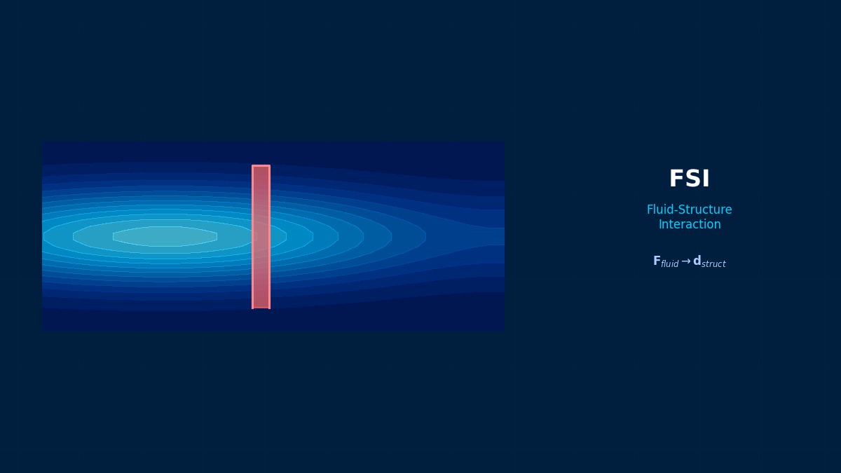
The cable itself is treated as a 2-degree-of-freedom (in-plane and lift directions) vibration system.
$F_L, F_D$ are the fluctuating lift and drag forces accompanying changes in the water film shape. The change in the water film position alters the lift coefficient, exciting unstable vibration.
So the water film position is the key.
The circumferential position of the upper rivulet significantly changes the aerodynamic characteristics of the cable. When the upper rivulet is positioned near the effective separation angle, the lift gradient becomes negative, causing galloping-type instability.
Water Droplets "Create" Vibration – The Curious Discovery of Rain-Wind Induced Vibration
Rain-wind induced vibration (RWV) was recognized academically relatively recently, starting with a report by Hikami & Shiraishi et al. in Denmark in 1988 on large-amplitude vibration of cable-stayed bridge cables. Until then, the phenomenon of "bridges shaking on rainy days" was known to exist but lacked a theoretical explanation. The key is that rivulet-like water rolls formed by rain create "aerodynamic asymmetry" in the cable cross-section. Each time the water film attached to the cable moves due to wind, the direction of lift changes, doing positive work and amplifying the vibration. It doesn't occur when dry, and if there's too much rain, the water runs off and it stops – the existence of this delicate "rainfall range" is at the core of RWV theory.
Computational Methods for Rainwind Vibration
Numerical Methods
How do you solve this three-way coupling (wind-rain-cable)?
There are full CFD approaches and semi-empirical approaches.
| Approach | Method | Accuracy | Computational Cost |
|---|---|---|---|
| 2D CFD + Water Film Model | RANS/LES + Thin Film Equation | Medium~High | Medium |
| 3D CFD-VOF | Multiphase Flow CFD | Very High | Very High |
| Quasi-Steady Aerodynamic Force Model | Wind Tunnel Test Data + ODE | Low~Medium | Low |
| Experimental Aerodynamic Coefficients + FEM | Wind Tunnel Data + Structural FEM | Medium | Low |
Do you directly resolve the water film using the VOF method?
It's possible, but the water film thickness is about 0.1~1 mm while the cable diameter is 100~200 mm, resulting in a scale ratio of 1:1000. Simultaneously meshing to resolve the water film and the external flow is extremely difficult, requiring AMR (Adaptive Mesh Refinement).
Practically, a semi-coupled approach is common: solving the flow around the cylinder with 2D CFD and separately solving for water film position and thickness with the thin film equation. There are research examples coupling a custom water film solver with OpenFOAM's pisoFoam.
How to Handle Rainwater Surface Tension – VOF or SPH?
To numerically reproduce the water roll on cable surfaces in RWV analysis, the method for tracking the gas-liquid interface is key. A representative method is VOF (Volume of Fluid), which represents the interface using fluid volume fraction. OpenFOAM's interFoam solver is widely used, but results vary greatly depending on how the contact angle (water repellency) on the cable surface is handled. Recently, SPH (Smoothed Particle Hydrodynamics) is gaining attention; it tracks water particles as particles, allowing more natural reproduction of behaviors like "water dripping" and "water film spreading on bridge cables." However, SPH is 1-2 orders of magnitude more computationally expensive than VOF, so practical analysis of full cable length still takes time.
Rainwind Vibration in Practice
Evaluation Methods in Design Practice
How is rain-wind induced vibration actually evaluated in bridge design?
In Japan, guidelines from the "Wind-Resistant Design Manual for Highway Bridges" (Japan Road Association) are followed. Occurrence conditions are wind speeds of 5~20 m/s, during rainfall, cable inclination angles of 20~60°, and when the relative angle between wind direction and cable is within a specific range.
Countermeasures
Are there ways to suppress rain-wind induced vibration?
Several countermeasures have been put into practical use.
| Countermeasure | Principle | Track Record |
|---|---|---|
| Cable surface dimple processing | Changes stable position of water film | Akashi Kaikyo Bridge |
| Helical fillet | Disrupts water film formation pattern | Tamagawa Sky Bridge |
| Damper installation | Dissipates vibration energy | Many cable-stayed bridges |
| Connecting cables | Connects cables to change modes | Tsurumi Tsubasa Bridge |
Can CFD simulation evaluate countermeasure effectiveness in advance?
CFD is used for shape optimization of dimples and fillets. Changes in aerodynamic coefficients due to surface roughness differences are evaluated with RANS to determine optimal shape parameters. However, full FSI including water film behavior remains at the research level due to computational cost issues.
RWV Field Measurement at Tamagawa Bridge – What Happened on a Typhoon Night
RWV of cable-stayed bridge cables has caused actual damage domestically as well. During Typhoon No. 18 in 2009, at a cable-stayed bridge in the Kanto region, heavy rain and winds exceeding 20 m/s overlapped, causing cables to vibrate with a maximum amplitude of about 80 cm. Local sensor records show vibration suddenly started around 2 AM and subsided around 5 AM when the rain weakened. This field measurement data led to a revision of design standards. Now, RWV verification is virtually mandatory for new designs of large cable-stayed bridges, and "wind tunnel testing + rain spray" dedicated RWV tests have become standard in bridge design consulting.
Rainwind Vibration: Software & Solver Comparison
Tool Comparison
What tools are available for analyzing rain-wind induced vibration?
| Tool | Purpose | Features |
|---|---|---|
| Ansys Fluent | 2D/3D CFD | VOF multiphase flow + dynamic mesh FSI |
| OpenFOAM | 2D/3D CFD | Easy implementation of custom water film models |
| Star-CCM+ | 2D/3D CFD | Built-in FSI coupling function |
| Ansys Mechanical | Structural FEM | System coupling with Fluent for FSI |
| Abaqus | Structural FEM | Co-simulation with Star-CCM+ etc. |
| In-house code (MATLAB/Python) | Prototype/Research | Flexible for new model development |
Which is better for RWV, commercial or open-source?
It depends on the purpose. For practical design verification, commercial software with proven track records and support is advantageous. For research exploring new models, open-source like OpenFOAM offers high flexibility. The key is whether the water film model can be implemented.
Recently, coupled analysis platforms like MBDyn (multibody dynamics) + OpenFOAM are also being used. This allows modeling of the entire cable system including supports.
The Reality of FSI Analysis – It's Not Just About the Software
When actually performing FSI analysis, the biggest bottleneck is often not the software itself but the "modeling know-how." For example, how to set the initial water film shape? How to model cable surface roughness? How to handle the contact angle of water? These modeling decisions often have a greater impact on results than the choice of solver. In the industry, it's common to first perform a parameter study using a simple model to understand trends, then proceed to detailed analysis. The key is not to aim for perfection from the start but to build up complexity step by step.
Selection Criteria
- Modeling Flexibility: Can custom water film models/equations be implemented?
- Coupling Capability: Does it support strong/weak coupling? Is Aitken relaxation available?
- Mesh Handling: Can it handle large scale differences? Is AMR supported?
- Computational Efficiency: Parallel scalability, solver convergence
- Support & Community: Availability of technical support, active user community
License Cost
Commercial software requires high initial investment but includes support. Open-source has no license fee but requires in-house expertise. Cloud-based HPC usage costs also need consideration.
Learning Curve
OpenFOAM has a steep learning curve but high potential. Commercial software is relatively easier to start with but may have limitations in advanced customization.
Future Outlook
AI/ML-assisted modeling, reduced-order models (ROM), and real-time simulation are emerging. The ability to integrate with these new technologies is also becoming a selection factor.
Related Topics
Experience the theory firsthand with the interactive simulator for this field
All Simulators