Thermal Buckling Analysis
Thermal Buckling Analysis: Theoretical Foundations
What is Thermal Buckling?
Does thermal buckling happen just because the temperature rises? Even without any load?
Yes. Roughly speaking, when a constrained structure is heated, it wants to expand but cannot, so compressive stress builds up. The moment that compressive stress exceeds a critical value, buckling occurs even with zero external load.
Huh, buckling with zero load goes against intuition, doesn't it? In what real-world situations does this actually happen?
Let me give you three familiar examples:
- Railway track "sun kink": Rails heat up in summer but are bolted to sleepers (ties), preventing longitudinal expansion. Compressive force accumulates, and when a certain temperature is exceeded, the rails buckle in a wavy pattern sideways. This causes train service suspensions.
- Aircraft skin panels: During supersonic flight, aerodynamic heating raises the skin temperature, but the skin is constrained by frames (skeleton), generating compressive stress and causing panel buckling.
- Thermal expansion of piping: High-temperature pipes in chemical plants, constrained between supports, can become compressed and buckle, leading to pipe bending accidents.
All follow the same mechanism: Constraint + Temperature Rise → Compressive Stress → Buckling.
I see! So "constraint" is the key. If it could expand freely, it wouldn't buckle.
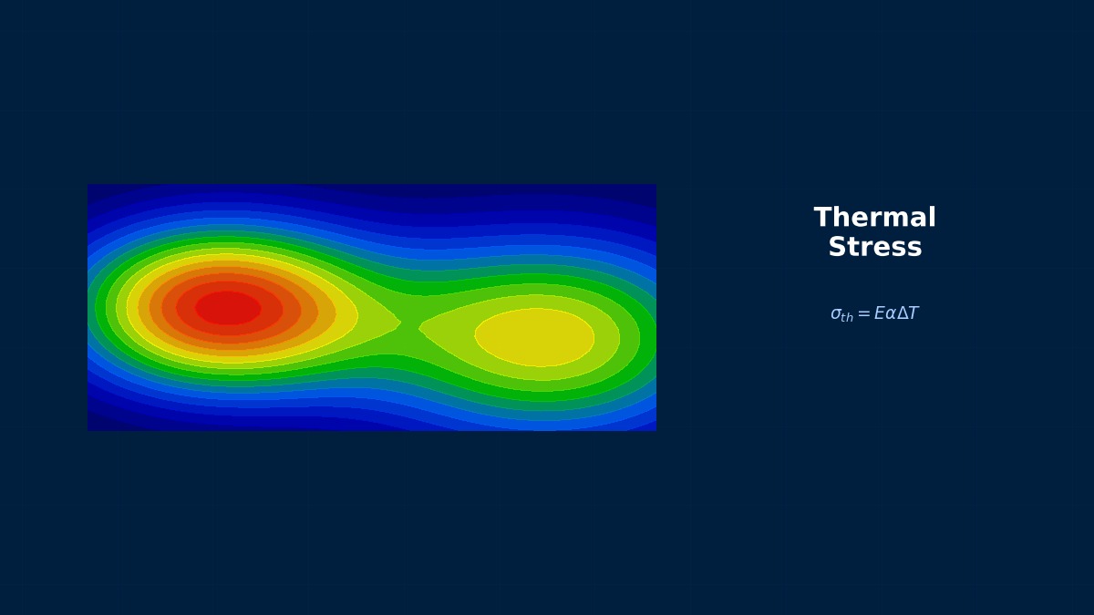
Exactly. With free ends, it would simply expand by $\Delta L = \alpha L \Delta T$ and that's it. But if both ends are fixed, the expansion is constrained to zero, so that amount is entirely converted into compressive stress $\sigma = E \alpha \Delta T$. This is the starting point of thermal buckling.
Thermal Stress Generation Mechanism
Can you explain the thermal stress formula in a bit more detail?
Consider a bar constrained in one axis. When the temperature rises by $\Delta T$, the free thermal strain is:
But if both ends are fixed, the total strain is zero ($\varepsilon_{\text{total}} = 0$), so elastic strain arises to counteract the thermal strain:
From Hooke's law, the compressive stress generated in the constrained structure is:
The negative sign means compression. For example, with steel ($E = 200\,\text{GPa}$, $\alpha = 12 \times 10^{-6}\,/\text{K}$) and $\Delta T = 50\,\text{K}$...
$\sigma = 200 \times 10^3 \times 12 \times 10^{-6} \times 50 = 120\,\text{MPa}$. A mere 50-degree temperature rise generates 120 MPa of compressive stress. For a thin plate, this stress is sufficient to cause buckling.
Theoretical Formula for Critical Temperature Difference
So, how do you specifically determine "at what temperature rise does buckling occur"?
Consider the most basic case: a rectangular plate simply supported on all four sides under uniform heating. This is the thermal version of Euler buckling theory.
The critical buckling stress from the plate buckling formula is:
Here, $k$ is the buckling coefficient (for simply supported four sides under uniaxial compression, $k = 4$), $t$ is the plate thickness, and $b$ is the short side width. Equating this with the thermal stress $\sigma = E \alpha \Delta T$ gives:
Wow, Young's modulus $E$ cancels out!
Good observation. Since thermal stress is $E \alpha \Delta T$ and the critical stress is also proportional to $E$, the $E$ factors cancel out. This means the critical temperature difference is determined solely by plate thickness, width, thermal expansion coefficient, and Poisson's ratio, and does not depend on Young's modulus. This is a characteristic unique to thermal buckling.
I'd like to get a feel for it with specific numbers. For example, for an aluminum plate ($\alpha = 23 \times 10^{-6}$, $\nu = 0.33$) with $t = 2\,\text{mm}$, $b = 200\,\text{mm}$, what happens?
Calculating with $k = 4$ (simply supported on four sides):
$\Delta T_{cr} = \dfrac{4 \times \pi^2 \times (0.002)^2}{12 \times 23 \times 10^{-6} \times (1 - 0.33^2) \times (0.2)^2} \approx 1.6\,\text{K}$
It buckles at just 1.6 degrees. This shows how susceptible thin aluminum panels are to thermal buckling. This is why thermal buckling is so important in aircraft skin design.
Formulation as an Eigenvalue Problem
How is it formulated in FEM?
Linear buckling analysis is formulated as an eigenvalue problem. Using the stress stiffness matrix $[K_\sigma]$ due to thermal stress:
The meaning of each symbol is as follows:
- $[K_0]$: Standard elastic stiffness matrix
- $[K_\sigma(T)]$: Stress stiffness matrix (also called geometric stiffness matrix) calculated from thermal stresses due to temperature $T$
- $\lambda$: Eigenvalue = critical temperature load multiplier
- $\{\phi\}$: Buckling mode shape
If $\lambda = 1$, buckling occurs exactly at the applied temperature load. If $\lambda = 0.5$, it buckles at half the temperature, which is dangerous. If $\lambda > 1$, it's on the safe side.
I see, so $\lambda$ acts like a safety factor.
Relationship Between Boundary Conditions and Critical Temperature
How much does the critical temperature change if you change the boundary conditions?
The buckling coefficient $k$ changes significantly with boundary conditions, so the critical temperature changes proportionally. Let's compare for a square plate ($a/b = 1$):
| Boundary Condition | Buckling Coefficient $k$ | $\Delta T_{cr}$ Multiplier (SS reference) |
|---|---|---|
| Simply Supported on All Sides (SSSS) | 4.0 | 1.0 |
| Clamped on All Sides (CCCC) | 10.67 | 2.67 |
| 2 Sides Clamped + 2 Sides Free (CCFF) | ≈2.2 | 0.55 |
| All Edges Free (with in-plane constraint) | 1.0 | 0.25 |
Simply clamping all four sides makes the critical temperature 2.7 times higher. Increasing fixed supports in design is a fundamental thermal buckling countermeasure. Conversely, structures with many free edges are weak.
Having the critical temperature differ by nearly a factor of 4 just by changing the fixation conditions is significant for design.
Computational Methods for Thermal Buckling Analysis
FEM Two-Step Analysis Procedure
What are the specific steps for analyzing thermal buckling with FEM?
The basic approach is a two-step process:
Step 1: Thermal Stress Analysis (Static Analysis with Thermal Load)
- Input temperature distribution $\Delta T(\mathbf{x})$ as a load
- Convert thermal strain $\varepsilon_{\text{th}} = \alpha \Delta T$ into equivalent nodal forces
- Solve $[K]\{u\} = \{F_{\text{th}}\}$ to obtain the stress field $\sigma_{ij}$
Step 2: Linear Buckling Eigenvalue Analysis
- Construct the stress stiffness matrix $[K_\sigma]$ from the stress field in Step 1
- Solve the eigenvalue problem $([K_0] + \lambda [K_\sigma]) \{\phi\} = \{0\}$
- The smallest positive eigenvalue $\lambda_1$ is the critical temperature multiplier
So if I input a temperature of 100 degrees in Step 1 and get $\lambda_1 = 0.6$, does that mean it buckles at 60 degrees?
Exactly. Since $\Delta T_{cr} = \lambda_1 \times \Delta T_{\text{ref}}$, the critical temperature difference is $0.6 \times 100 = 60$ degrees. In practice, a safety factor of 1.5 to 2.0 is applied, so the design allowable temperature becomes $\Delta T_{\text{allow}} = 30 \sim 40$ degrees.
Element Selection and Formulation
What kind of elements should be used for thermal buckling analysis?
It depends on the structure's shape:
| Structure Type | Recommended Element | Notes |
|---|---|---|
| Thin plate panels | Shell elements (S4R, SHELL181, etc.) | Use 5–7 integration points through thickness to capture bending gradients |
| Thick plates / Block bodies | Solid elements (C3D20R, SOLID186, etc.) | Mesh with at least 3–4 layers through the thickness |
| Rails / Beams | Beam elements (B31, BEAM188, etc.) | Cannot capture local buckling of thin-walled parts; use in conjunction with shell elements |
| Piping | Pipe/Shell elements | Sufficient circumferential divisions are needed to capture circumferential buckling modes |
Shell elements are used a lot. What's the effect of the number of integration points through the thickness?
If there's a temperature gradient through the thickness, too few integration points cannot accurately capture the bending stress distribution. For example, with one-sided heating, a linear temperature distribution through the thickness occurs. If there are only 3 integration points, the bending thermal stress might be underestimated. In practice, at least 5, preferably 7 points are recommended.
Nonlinear Post-Buckling Analysis
Is linear buckling analysis sufficient? What if I want to know the post-buckling behavior?
Good question. Linear buckling tells you "when it buckles" but not "what happens after buckling." To track post-buckling behavior, nonlinear static analysis (geometric nonlinearity) is required.
The procedure is as follows:
- Obtain the buckling mode shape $\{\phi\}$ from linear buckling analysis.
- Scale this mode shape and add it to the geometry as an initial imperfection (typically 10–50% of the plate thickness).
- Perform a nonlinear static analysis (NLGEOM=ON) with the temperature load increased incrementally.
- Track the load-displacement curve (Riks method or Arc-length method).
What happens if you don't include an initial imperfection?
With perfect geometry, the solution is not unique at the bifurcation point, and the solver may fail to capture the buckling. In nonlinear analysis, it's standard practice to include an initial imperfection based on the premise that "perfect structures do not exist in reality." Real structures have tiny imperfections due to manufacturing errors, so a model with initial imperfections is actually more realistic.
Key Points for Solver Settings
Are there any important points to watch for in solver settings?
Yes, there are many critical details. Let me organize them:
| Setting Item | Recommended Value | Reason |
|---|---|---|
| Number of eigenvalues to find | 10–20 | Check influence of higher modes, not just the lowest |
| Eigenvalue solver | Lanczos method | Stable and fast for large-scale models |
| Temperature reference temperature | Stress-free temperature | Many accidents occur due to misconfiguration causing all stresses to be offset |
| NLGEOM (Nonlinear) | ON | Mandatory for post-buckling tracking |
| Temperature-dependent material properties | Include if ΔT > 50 K | Significant variation of E and α with temperature can change critical temperature by 10–20% |
| Geometric imperfection amplitude | t/10 to t/20 | t = plate thickness; typical manufacturing tolerance |
So it's important to be careful about the reference temperature setting?
Absolutely critical. The thermal stress is $\sigma = E \alpha (T - T_{\text{ref}})$. If $T_{\text{ref}}$ is set incorrectly, the entire stress field is wrong. For example, if the structure is assembled at room temperature (293 K) and is then heated to 373 K, the reference temperature must be 293 K, and $\Delta T = 80$ K. Setting $T_{\text{ref}} = 0\,\text{K}$ by mistake would give a completely different (and erroneous) stress state.
Related Topics
Experience the theory with interactive simulators in this field
Euler Buckling Thermal Stress