Industrial Furnace Simulation
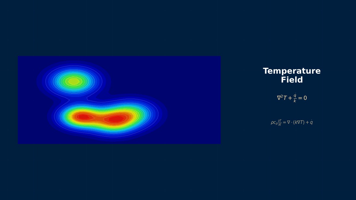
Theory: radiation heats the surface, conduction the interior
Overview
We're asked to raise throughput of a reheating furnace before rolling. Should we just raise the furnace temperature?
It's not that simple. Above 1000 °C, heat reaches the slab surface almost entirely by radiation from furnace walls and combustion gases. The surface heats quickly, but heat reaches the centre only by conduction through the steel. Rolling needs uniform temperature through the thickness (soaking), not just a hot surface, so throughput is usually set by how the centre heats. A hotter furnace heats the surface faster, but the surface nears its limit sooner and oxidation increases. First compute surface and centre temperature histories to see what's limiting.
Surface heat flux
$\varepsilon_{eff}$ is the effective emissivity between furnace and slab (set by wall, gas and slab emissivities and view factors). Expressed as an equivalent coefficient $h_{rad}$, radiation grows with temperature.
Soaking-time scaling
The time for heat to penetrate scales with half-thickness squared over thermal diffusivity; doubling thickness pushes soaking time toward four times.
Regenerative burners and furnace efficiency
Reheating furnaces burn large amounts of fuel, so heat recovery has long been pursued. The regenerative furnace invented by the Siemens brothers in the mid-19th century stored exhaust heat in brick checkerwork and alternated flow direction to preheat combustion air. This idea, which enabled open-hearth steelmaking, returned in the late 20th century as compact regenerative burners, and Japan pursued high-performance industrial furnaces recovering much of the exhaust heat. Modern furnace analysis couples combustion, radiation and product heat transfer to optimise both fuel use and throughput.
Worked example: heating a slab
A 20 °C slab heated on both faces in a 1250 °C furnace (effective emissivity 0.8, convection 20 W/m²K, conductivity 30 W/mK, volumetric heat capacity 5.0 MJ/m³K). Time for the surface to reach 1150 °C and for the centre to come within 30 K (soak):
| Thickness | Surface 1150 °C | Soaked | Surface / centre at soak |
|---|---|---|---|
| 100 mm | 26 min | 32 min | 1195 / 1165 °C |
| 200 mm | 55 min | 85 min | 1224 / 1194 °C |
| 250 mm | 70 min | 120 min | 1230 / 1200 °C |
Initial heat flux is 268 kW/m². The equivalent radiative coefficient is 335 W/m²K at a 600 °C surface, 500 at 1000 °C and 610 at 1200 °C — over ten to thirty times the 20 W/m²K convection.
Doubling thickness makes soaking take 2.7 times as long.
Centre heating is conduction-controlled, so it stretches almost with thickness squared. What about a hotter furnace? The table below compares at 200 mm: the surface reaches 1150 °C 12 minutes sooner, but soaking shortens by only 3 minutes, because heat flow from surface to interior is limiting. Conversely, if emissivity drops (scale, dirty walls), soaking lengthens by 14 minutes. To raise throughput, revisiting product spacing, radiative exposure and zone-by-zone temperature settings usually helps more than furnace temperature.
| Condition (200 mm) | Surface 1150 °C | Soaked |
|---|---|---|
| Base (1250 °C, emissivity 0.8) | 55 min | 85 min |
| Furnace 1300 °C | 43 min | 82 min |
| Emissivity 0.6 | 71 min | 99 min |
Analysis workflow
- Solve combustion and flow with CFD for gas temperature and composition (CO₂ and H₂O drive radiation).
- Compute radiation among walls, gases and product, including view factors and gas absorption.
- Solve product conduction with temperature-dependent properties (including steel transformation heat).
- For moving product, follow zone temperatures and residence times together.
- Compare with embedded (trailing) thermocouple measurements in the product.
“A hotter furnace only added scale”
To raise throughput, a reheating furnace's setpoint was raised by 50 °C, but the discharged slab centre temperature barely changed, while surface scale (oxide) increased and yield fell. Tracking surface and centre temperatures by heat-transfer analysis showed internal conduction was limiting, so the hotter furnace didn't speed centre heating. Redistributing heat — hotter early zones to put heat in sooner, cooler later zones for soaking — raised throughput on the same fuel and reduced scale. When and where heat goes in matters.
Common mistakes
Mistakes and fixes
| Mistake | Effect | Fix |
|---|---|---|
| Judging by surface temperature | Centre underheated | Evaluate centre difference |
| Constant radiative coefficient | Temperature dependence missed | Use the fourth-power law |
| Idealised emissivity | Heating time underestimated | Account for scale and fouling |
| Assuming hotter is faster | Only more scale | Revisit zone distribution |
| Ignoring shadowing between products | Temperature non-uniformity | Compute view factors |
I'd like to try related calculations.
Try the furnace efficiency calculator, view factor calculator and radiation network simulator. Related processes include quench heat treatment, kiln analysis and casting thermal analysis.
Related Topics
Experience the theory firsthand with the interactive simulator for this field
All Simulators