Mushy Zone Model
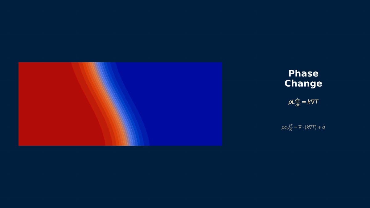
Theory: the temperature range where solid and liquid mix
Overview
CFD of an aluminium-alloy casting puts shrinkage porosity in the wrong place. What should I revisit?
First check the mushy-zone treatment. Alloys don't freeze at one temperature like pure metals; between liquidus and eutectic they become a mixture of dendritic crystals and liquid. How far liquid can flow through it to feed shrinkage decides where porosity forms. Two things matter in the model: the law giving solid fraction from temperature, and the resistance constant setting how strongly flow is stopped in the partially solid region. Both change results greatly depending on choice.
Solid-fraction laws
$k$ is the equilibrium partition coefficient, $T_m$ the pure-metal melting point and $T_L$ the liquidus. The lever rule assumes full diffusion even in the solid (equilibrium); Scheil assumes none in the solid.
The Darcy term that stops flow
The term added to the momentum equation in the enthalpy–porosity method. It rises sharply as liquid fraction $f_l$ falls, driving velocity to zero where solid. $A_{mush}$ is the mushy-zone constant; $\epsilon$ is a small number avoiding division by zero.
Composition unevenness in castings
The Scheil equation was presented in 1942 by Scheil in Germany to explain segregation — solute rejected into the liquid during solidification. It simply explains why impurities gather at the centre or last-to-freeze regions of castings. In the 1980s Voller and Prakash proposed the enthalpy–porosity method, treating the mushy zone as a porous medium to stop flow, letting solidification and flow be solved on the same grid. Much of today's casting simulation rests on these two ideas.
Worked examples
Example 1: solid fraction of Al-4%Cu
Pure-aluminium melting point 660 °C, liquidus slope −3.4 K/%, partition coefficient 0.17, eutectic 548 °C. Liquidus is 646.4 °C; the lever-rule solidus is 580 °C.
| Temperature | 640 °C | 620 °C | 600 °C | 580 °C | 560 °C | 548 °C |
|---|---|---|---|---|---|---|
| Lever rule | 0.386 | 0.795 | 0.932 | Solid | Solid | Solid |
| Scheil | 0.372 | 0.727 | 0.833 | 0.882 | 0.910 | 0.921 |
With Scheil, the remaining 7.9% freezes at once at the eutectic. The final solidification range is 32 K wider than with the lever rule.
Example 2: effect of the mushy-zone constant
The Darcy coefficient relative to the viscous term (viscosity 1.3×10⁻³ Pa·s, length 1 mm):
| Liquid fraction | 0.99 | 0.9 | 0.5 | 0.1 |
|---|---|---|---|---|
| A = 10⁵ | 0.008 | 1.05 | 153 | 3.1×10⁴ |
| A = 10⁸ | 7.9 | 1,050 | 1.5×10⁵ | 3.1×10⁷ |
Just changing the constant makes flow at liquid fraction 0.9 differ by a factor of 1,000.
Right. A small constant lets liquid flow deep into largely solid regions; a large one stops flow as soon as solidification begins. Porosity forms where liquid can no longer feed, so this constant changes both where porosity forms and how big it is. Don't trust general-purpose defaults (often about 10⁵); set it from permeability derived from dendrite arm spacing, or match experimental solidification. Calibrate it per material together with the solid-fraction law.
Analysis workflow
- Collect liquidus, solidus, eutectic and partition coefficient from the phase diagram.
- Choose lever, Scheil or intermediate models according to cooling rate.
- Set the mushy-zone constant from permeability based on dendrite arm spacing (estimated from cooling rate).
- Solve shrinkage and feeding, applying porosity criteria such as Niyama.
- Compare with sections or X-ray results and revise the constants.
“Porosity appeared higher than predicted”
In casting an aluminium-alloy wheel, porosity predicted at the centre of a thick section appeared slightly higher in the real part. The solidification model used the lever rule with a 580 °C solidus. Switching to Scheil lengthened the time liquid persisted down to the eutectic, and the last-to-freeze location moved upward. Tuning the mushy-zone constant to test results then matched the porosity location well. Both the solid-fraction law and the flow resistance must suit the material.
Common mistakes
Mistakes and fixes
| Mistake | Effect | Fix |
|---|---|---|
| Lever rule at fast cooling | Solidification end predicted too early | Use Scheil |
| Default mushy constant | Porosity misplaced | Calibrate by permeability or tests |
| Ignoring eutectic latent heat | Cooling-curve arrest missed | Include eutectic |
| Ignoring shrinkage | Porosity unpredictable | Solve density change and feeding |
| Grid coarse versus mushy zone | Flow arrest misplaced | Several cells across the range |
I'd like to learn related topics.
Estimate solidification time with the Chvorinov solidification-time tool. Related topics include the Stefan problem, the enthalpy method, casting solidification, melting and solidification and casting thermal analysis.
Related Topics
Experience the theory firsthand with the interactive simulator for this field
All Simulators