Fluid-Structure Interaction of Dams During Earthquakes
Fluid-Structure Interaction of Dams During Earthquakes: Theoretical Foundations
Overview of the Phenomenon
Why does fluid-structure interaction become important for dams during earthquakes?
When a dam body vibrates due to seismic motion, the water in the reservoir behind it acts on the dam face as dynamic pressure. This hydrodynamic pressure increases the dam's response and can, in some cases, threaten the safety of the structure. Since Westergaard's (1933) classic study, consideration of hydrodynamic pressure has been essential in the seismic design of dams.
Governing Equations
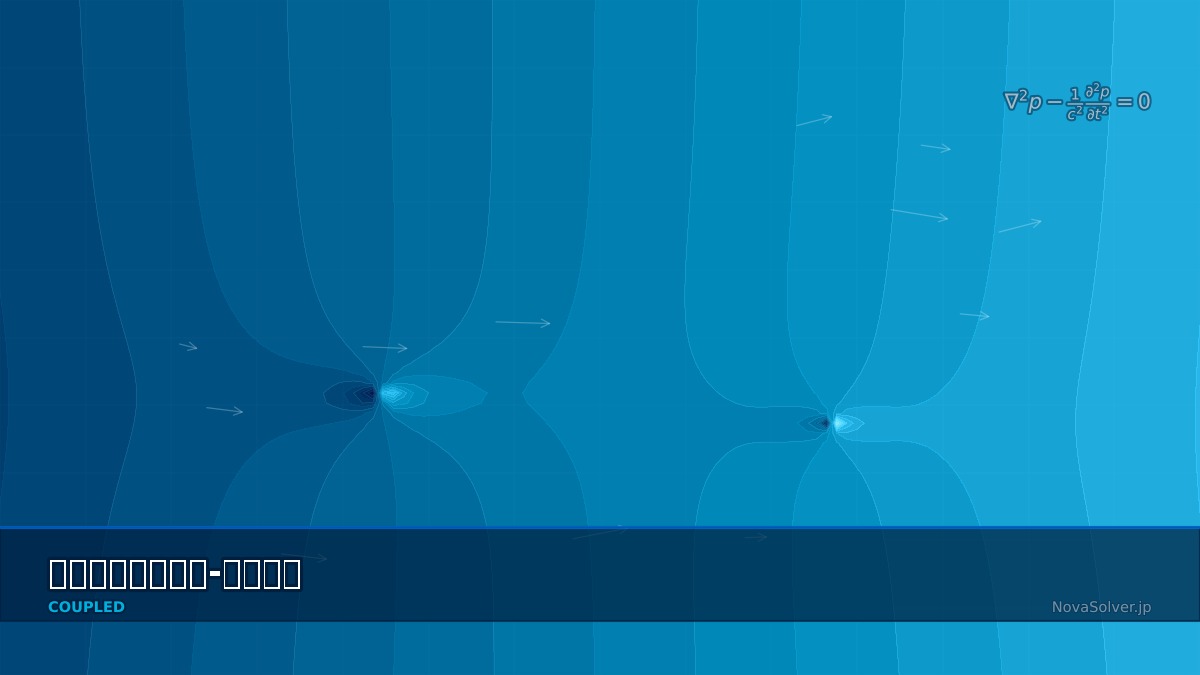
How is the reservoir water treated?
Assuming water as an inviscid, incompressible fluid leads to the Laplace equation, but for seismic response, the wave equation considering compressibility is often used.
$c$ is the speed of sound in water (approx. 1440 m/s). The boundary condition on the dam face is,
$\ddot{u}_n$ is the normal direction acceleration of the dam face.
The dam body is described by the structural mechanics equation of motion.
$\{F_{eq}\}$ is the seismic inertial force, and $\{F_{hydro}\}$ is the load vector due to hydrodynamic pressure.
Is Westergaard's added mass method still used?
It is still used as a simplified method. It converts the hydrodynamic pressure distribution for a rigid dam into added mass.
$H$ is the water depth, $y$ is the depth from the water surface. However, it cannot account for dam flexibility or the effects of finite reservoir length, so FEM-BEM coupling is necessary for detailed evaluation.
The "Natural Frequency Showdown" Between Dam and Water — The Amplification Trap Triggered by Seismic Waves
Concrete dams may appear "super rigid," but their natural frequency changes significantly when integrated with reservoir water. For example, theoretical studies show that the natural frequency of an empty dam versus a full dam can decrease by 20-40% due to the added mass effect of fluid inertia. In the 1971 San Fernando earthquake, a rockfill dam avoided collapse despite experiencing shaking exceeding the design seismic force. Subsequent investigations revealed the ironic good fortune that "the full water state lowered the frequency, shifting it away from the predominant period of the main seismic waves." Without understanding the theory, the seismic safety assessment can change drastically based solely on whether the dam is full or empty.
Computational Methods for Fluid-Structure Interaction of Dams During Earthquakes
For the dam body, discretization with FEM (Solid Elements) and for the reservoir, acoustic fluid elements are standard. Abaqus's AC3D series elements or Ansys's FLUID30 elements are used.
The equation of motion for the coupled system takes the following form.
$R$ is the coupling matrix, constructed from area integrals at the fluid-structure interface.
What about time integration?
The Newmark-β method ($\beta = 0.25, \gamma = 0.5$) or HHT-α method are standard. Earthquake input is set as an acceleration time history at the foundation base. The sampling interval is typically 0.01 seconds, but 0.005 seconds or less is needed to consider high-frequency components.
Treatment of Infinite Reservoir Extent
The reservoir extends infinitely upstream, right? How is that handled?
Set the Sommerfeld radiation condition (non-reflective boundary) at the upstream end. In Ansys, it's implemented as an impedance boundary; in Abaqus, as a Non-Reflecting Boundary Condition. Alternatively, one can set the model boundary at a distance equivalent to 5-10 times the water depth from the dam face and place an absorbing boundary there.
The "Overreliance" on the Westergaard Formula — Design Errors Caused by a Simple Formula
When calculating seismic hydrodynamic pressure on dams, the "Westergaard formula (1933)" found in textbooks is still sometimes used. This formula is an analytical solution assuming a vertical plane dam subjected to vertical seismic acceleration, making calculation very simple. However, the problems are that it produces errors when applied to arch dams or trapezoidal cross-section dams, and it ignores "dam-water-foundation rock coupled vibration." In fact, in the analysis of a certain gravity dam, the hydrodynamic pressure from the Westergaard formula was overestimated by more than 30% compared to FEM coupled analysis results. While one might think "a simple formula is on the safe side," overestimation leads to unnecessary reinforcement costs — the need for numerical methods also lies in cost reduction.
Fluid-Structure Interaction of Dams During Earthquakes in Practice
For a typical arch dam,
1. Create FE model of the dam body (Solid Elements, 20-node hexahedral elements are desirable).
2. Model the foundation rock (extent of 2-3 times the dam height).
3. Acoustic fluid model for the reservoir (distance of 3-5 times the water depth upstream from the dam face).
4. Define the fluid-structure interface (tie constraint).
5. Set earthquake input wave (uniform excitation or deconvolved motion at the foundation base).
Why is modeling the foundation rock important?
The dam's response is determined by the three-way coupling of dam-foundation-reservoir. Ignoring the mass effect (inertia effect) and radiation damping of the foundation rock leads to overestimation of the response. The assumption of a mass-less foundation is conservative but can predict unrealistically large stresses.
Material Models
What material model is used for concrete dams?
Perform screening analysis with linear elasticity, and switch to the Concrete Damaged Plasticity (CDP) model if necessary. Abaqus's CDP model expresses stiffness degradation using compression and tension damage parameters $d_c, d_t$.
| Parameter | Typical Value (Mass Concrete) |
|---|---|
| Young's Modulus | 25-35 GPa |
| Poisson's Ratio | 0.18-0.20 |
| Density | 2400 kg/m³ |
| Tensile Strength | 2-4 MPa |
| Compressive Strength | 20-40 MPa |
| Damping Ratio | 5% |
The "Terror of a 1m Water Level Difference" — Dam FSI in Practice, as Told by Field Engineers
In dam management, it's often said, "Lower the water level before an earthquake." There is quantitative basis for this. Reports indicate that lowering the water level by just 10m below the design full water level can significantly reduce hydrodynamic pressure load by area ratio, improving tensile stress at the dam bottom by 15-25% in some cases. However, one might think, "If you lower the water, doesn't the flood risk downstream disappear?" But rapid water level manipulation risks inducing drawdown phenomena or piping (formation of water channels). In practice, it's crucial to decide in advance the criteria for "gradually lowering the water level before an earthquake." Major dams in Japan have specific water level management procedures incorporated into their earthquake response manuals.
Fluid-Structure Interaction of Dams During Earthquakes: Software & Solver Comparison
Tool Comparison
What software is available for seismic FSI analysis of dams?
Let's organize the main tools.
| Tool | Fluid Model | Features |
|---|---|---|
| Abaqus | Acoustic Elements (AC3D) | Supports CDP model. Rich experience in dam analysis. |
| Ansys Mechanical | FLUID30/220 Elements | Acoustic-structure coupling. Strong in large-scale parallelization. |
| DIANA FEA | Acoustic Elements | Specialized for concrete. Automatic Westergaard setting. |
| LS-DYNA | ALE |
Related Topics
Experience the theory firsthand with the interactive simulator for this field
All Simulators