One-Way Fluid-Structure Interaction
One-Way Fluid-Structure Interaction: Theoretical Foundations
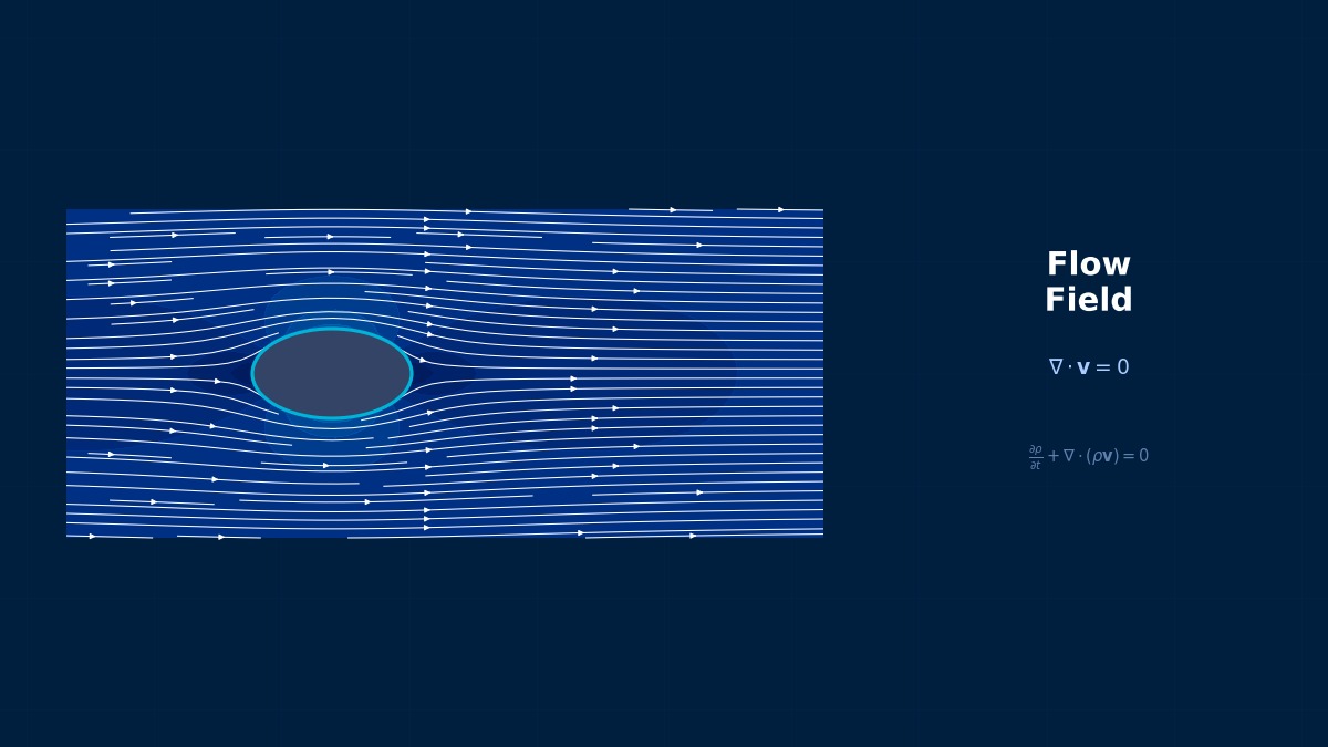
Concept of One-Way FSI
Professor, what's the difference between One-Way FSI and Two-Way FSI?
In One-Way FSI, the pressure and shear forces obtained from the fluid analysis are simply transferred as load conditions for the structural analysis, assuming that the structural deformation does not affect the fluid. In other words, the information flow is one-way: "Fluid → Structure".
This assumption is valid when the structural deformation does not significantly alter the fluid field. Specifically,
1. The structural displacement is very small compared to the characteristic length ($\delta/L \ll 1$)
2. The natural frequency of the structure is sufficiently separated from the fluid excitation frequency
3. The structural density is sufficiently larger than the fluid density ($\rho_s / \rho_f \gg 1$)
What kind of specific problems can it be used for?
Sufficient accuracy can be obtained with One-Way FSI in the following scenarios.
| Application | Fluid | Structure | Evaluation Items |
|---|---|---|---|
| Automotive Exterior Panels | Driving Wind | Steel Panels | Deformation & Stress due to Wind Pressure |
| Fluid Forces on Piping | Internal Flow | Piping Structure | Stress due to Pressure Load |
| Wind Load on Buildings | Wind | Steel/RC Structure | Wind Pressure Distribution, Inter-story Displacement |
| Turbo Machinery Blades | Steady Aerodynamic Forces | Blade | Static Stress from Centrifugal Force + Aerodynamics |
| Thermal Deformation of Electronics | Cooling Airflow | Substrate | Temperature Distribution → Thermal Stress |
So it's used when deformation is small and there's no need to feed it back to the flow field, right? Is the computational cost also significantly cheaper than Two-Way?
Overwhelmingly cheaper. Since you only solve CFD and FEA once each, the computation time is on the order of 1/10 to 1/100 compared to Two-Way FSI (which solves iteratively dozens of times). It's very efficient for initial design screening or rough structural strength estimation.
The Price Paid for "Omitting" One-Way FSI in Bridge Design
One-Way FSI is a valid simplification when "the influence from fluid to structure is small," but misjudging this can lead to serious consequences. In fact, there is a case where a suspension bridge was designed by completely separating fluid force analysis and structural analysis, treating the dynamic components of fluid loads with static conversion. After construction, vibrations during strong winds far exceeded design predictions. This failure was caused by the assumption that "solving separately should yield the same answer." Before choosing One-Way FSI, it is essential to quantitatively verify the validity of its assumptions.
Computational Methods for One-Way Fluid-Structure Interaction
Data Transfer Methods
When passing CFD results to FEA, I think the meshes are different. How is the data transferred?
Data mapping from CFD mesh (usually fine) to FEA mesh (usually coarse) is required. The main methods are as follows.
| Method | Principle | Accuracy | Conservation |
|---|---|---|---|
| Nearest neighbor | Copy value from nearest point | Low | No |
| Inverse distance weighting | Weight by inverse distance | Medium | No |
| Conservative mapping | Weight by area/volume | High | Yes (Force sum conserved) |
| Profile preserving | Interpolation based on shape functions | High | No (Distribution shape preserved) |
| RBF Interpolation | Interpolation using radial basis functions | Very High | Configuration dependent |
Conservative mapping is crucial for force (pressure/shear) transfer. This guarantees that the total force on the CFD surface exactly matches the total force on the FEA surface. This option is available in Ansys System Coupling or STAR-CCM+ Co-Simulation.
What happens without conservation?
For example, when transferring a CFD result of 100 N lift to FEA, the integrated value on the FEA side becomes 95 N or 105 N. This disrupts the overall force balance of the structure, introducing errors into deformation and reaction force results. Especially when overall load is a design criterion (e.g., blade root stress), conservative mapping is essential.
Time History Data Transfer
How about when passing unsteady CFD results to structure?
There are two approaches.
1. Instantaneous Value Transfer: Input the pressure distribution from each CFD time step into FEA transient analysis. Mapping is performed for all time history steps. High accuracy but data volume becomes enormous.
2. Statistical Quantity Transfer: Transfer time-averaged pressure and pressure fluctuation RMS (or PSD). Evaluate static loads with time average and fatigue loads with RMS basis. Less data, practical for real work.
How do you get structural fatigue loads from PSD (Power Spectral Density)?
In random vibration analysis (Nastran SOL 111/112), calculate stress PSD using pressure PSD as input, then estimate fatigue life using Dirlik or Steinberg methods. This method is widely used in analyses like rocket fairing acoustic loads.
File-Based vs. Software Coupling
For One-Way FSI data exchange, is file-based transfer okay?
For One-Way FSI, file-based is sufficiently practical.
| Method | Advantages | Disadvantages |
|---|---|---|
| File-Based (CSV, CGNS) | Simple, no software dependency | Manual mapping, no conservation guarantee |
| Within Ansys Workbench | Complete within GUI, automatic mapping | Limited to Ansys products |
| System Coupling | Conservation guaranteed, automated | License required |
| Python script | Flexible, can be automated | Requires custom implementation |
For file-based, export wall pressure from Fluent in CGNS/EnSight format and load it as Imported Pressure in Ansys Mechanical or Abaqus. Mapping accuracy depends on the software's import function, so it's important to verify the total force after transfer.
"Data Mapping" Accuracy Determines the Fate of One-Way FSI
The most overlooked problem in One-Way FSI is interface data mapping. CFD meshes and structural meshes are typically created with different shapes and densities, so nodes don't match. Using nearest neighbor interpolation without care for force or pressure mapping can introduce non-trivial errors, causing integrated load values to deviate by a few percent. There are reported cases where this causes 10-20% error in structural peak stress. The perception that "data transfer is a simple task" can be the cause of unexpected accuracy degradation.
One-Way Fluid-Structure Interaction in Practice
One-Way FSI in Ansys Workbench
How do I actually set this up in Ansys Workbench?
Here's the workflow:
Step 1: Mesh Creation
Create CFD and FEA meshes separately. The CFD mesh should be fine enough to resolve boundary layers; the FEA mesh can be coarser (typically 2–10 times larger elements).
Step 2: CFD Analysis (Fluent)
Run steady or transient CFD. Ensure convergence is adequate. Export pressure field on the fluid-structure interface.
Step 3: Pressure Mapping
In Workbench's Mechanical module, use Geometry → Imported Loads → Pressure to load the CFD pressure field. Specify the mapping method (nearest node, conservative, etc.).
Step 4: FEA Structural Analysis
Run static or transient structural analysis with the mapped pressure as a load. Solve for stress and displacement.
Can I automate this in Python?
Yes. Use PyFluent and PyMechanical (Ansys Python libraries) to script the entire workflow. Extract pressure data from Fluent via API, perform custom mapping with scipy, and apply loads to Mechanical. This is especially useful for parametric design optimization or batch processing.
Example pseudo-code:
# 1. Run CFD in Fluent
session = launch_fluent()
case = session.file.read(case="airfoil.cas")
session.solver.solve()
pressure_field = session.results.scalar["pressure-coefficient"]

# 2. Get FEA mesh nodes
mech_nodes = extract_structural_nodes()

# 3. Map pressure (nearest-neighbor or RBF)
mapped_pressure = map_pressure(pressure_field, mech_nodes)

# 4. Apply to Mechanical and solve
session_mech = launch_mechanical()
session_mech.geometry.import_pressure(mapped_pressure)
session_mech.solve()
stress = session_mech.results.stress