Tube Bundle Flow-Induced Vibration Analysis
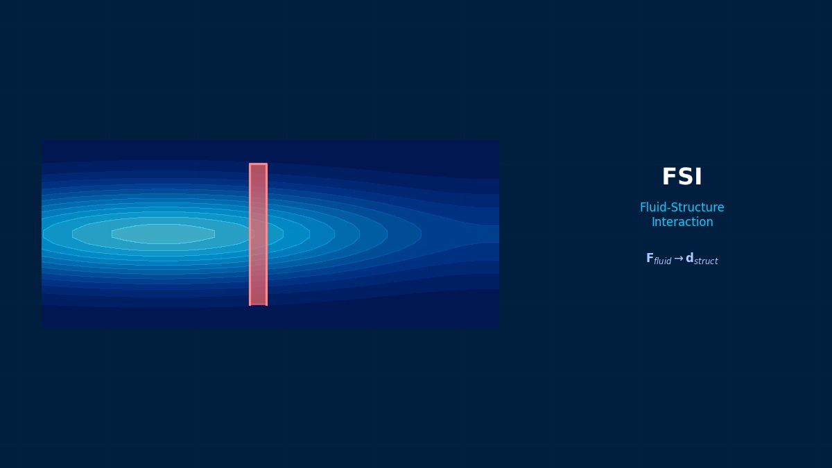
Theory: flow and tube motion reinforcing each other
Overview
We're considering a modification to raise flow through a shell-and-tube heat exchanger. Should tube vibration be a concern?
Very much so. Crossflow over tubes creates forces that shake them. Most dangerous is fluidelastic instability: tube motion alters the surrounding flow, which drives the tube further — a self-reinforcing loop. Above a certain velocity (the critical velocity), amplitude jumps suddenly, and tubes can rub against neighbours or baffles and perforate within a short time. Before raising flow, compute tube natural frequency and critical velocity to confirm there's margin.
Tube natural frequency
First natural frequency treating a baffle-supported tube as a pinned–pinned beam. $m$ includes the tube, fluid inside, and added mass from fluid moving outside (coefficient $C_m$).
The Connors equation
$D$ is tube OD, $\zeta$ the damping ratio and $K$ a constant set by tube pattern and flow direction (about 2.4–3 in design). $f_s$ is vortex-shedding frequency, with Strouhal number $St$ about 0.2–0.5 depending on pattern.
What nuclear heat exchangers taught
In the 1960s–70s, nuclear steam generators and large heat exchangers repeatedly suffered tube perforations soon after start-up. Investigations found flow-induced vibration making tubes rub against their supports. In 1970 Connors, from wind-tunnel tests on tube rows, gave an equation for the critical velocity of the instability arising from tube–flow reinforcement. Data on its constant and on damping accumulated, and vibration assessment entered the US heat-exchanger standard (TEMA) and ASME guidance.
Worked example: varying baffle span
Steel tube 19.05 mm OD, 1.65 mm wall, water inside and out, added-mass coefficient 1.5, damping ratio 1.5%. Mass per length is 1.33 kg/m (tube 0.71, water inside 0.20, added mass 0.43):
| Baffle span | Natural frequency | Critical velocity (K = 3.0) | Critical velocity (K = 2.4) | Shedding lock-in velocity |
|---|---|---|---|---|
| 400 mm | 223 Hz | 7.5 m/s | 6.0 m/s | 12.9 m/s |
| 600 mm | 99 Hz | 3.3 m/s | 2.7 m/s | 5.7 m/s |
| 800 mm | 56 Hz | 1.9 m/s | 1.5 m/s | 3.2 m/s |
At a gap velocity of 2 m/s, 600 mm is safe but 800 mm is dangerous.
Right. Natural frequency is inversely proportional to span squared, so a small increase in span cuts critical velocity sharply. At 800 mm even K = 3 gives 1.9 m/s, below 2 m/s. K scatters widely in experiments, and design often uses a conservative value around 2.4; then even 600 mm gives 2.7 m/s — only 1.35 times margin over 2 m/s. The basic practice is to allow for uncertainty in K and damping and keep ample margin over flow velocity (e.g. about 1.3–2 times). For a flow-increase modification, also check where velocity peaks locally, such as near inlets and outlets.
Assessment workflow
- Find the gap-velocity distribution (higher near inlets, outlets and baffle windows).
- Compute tube natural frequencies including support conditions and added mass.
- Compute fluidelastic critical velocity considering ranges of K and damping.
- Check vortex-shedding and acoustic frequencies don't coincide with tube or shell natural frequencies.
- Estimate wear life at supports from turbulent-buffeting amplitude.
“Only a few tubes by the inlet failed”
After a flow-increase modification to a heat exchanger, only a few tubes directly beneath the shell inlet nozzle perforated within a year. Across the bundle the average velocity had margin against critical, but flow concentrated beneath the inlet, reaching nearly twice the average locally. CFD of the inlet region showed those tubes exceeded critical velocity. An impingement plate to spread the flow and tighter baffle spacing in that zone stopped the damage.
Common mistakes
Mistakes and fixes
| Mistake | Effect | Fix |
|---|---|---|
| Assessing by average velocity | Local instability missed | Map velocity distribution |
| Ignoring added mass | Frequency overestimated | Include fluid inside and out |
| Optimistic K | Critical velocity overestimated | Conservative K and margin |
| Assuming high damping | Instability missed | Data-based damping |
| Ignoring acoustic resonance | Loud noise and vibration | Check shell acoustic modes |
I'd like to learn related topics.
Try the Kármán vortex simulator and damped natural frequency calculator. Related fluid–structure topics include vortex-induced vibration, aeroelasticity and flutter, hydroelasticity and water hammer.
Related Topics
Experience the theory firsthand with the interactive simulator for this field
All Simulators