Multiphysics Topology Optimization — Simultaneous Optimization of Structure, Heat, and Fluid Using the SIMP Method
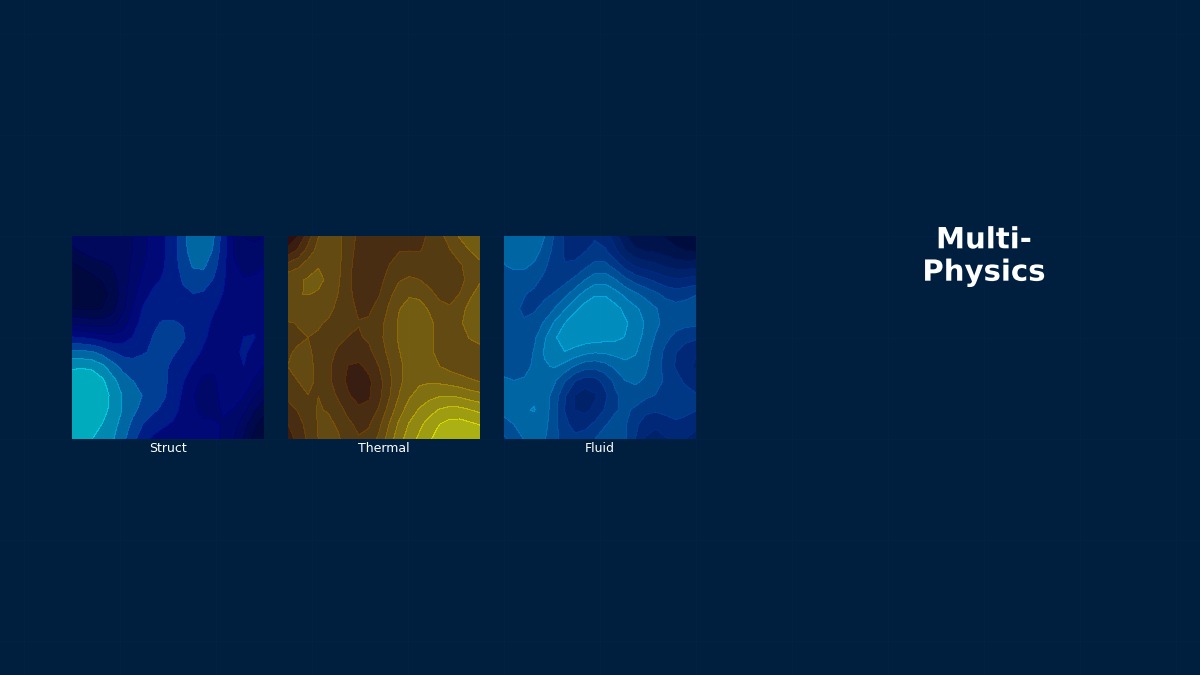
Theory: searching for where material goes with continuous variables
Overview
I want a bracket supporting a heat-generating part to be light and good at dissipating heat. Can topology optimisation handle structure and heat together?
Yes. Topology optimisation divides the design region into small elements and decides whether each gets material, searching for the best shape. Choosing 0 or 1 for each is combinatorially huge, so SIMP makes density a continuous 0–1 variable and scales properties with a power of density. Put both stiffness and heat conduction in the objective and you get a shape that balances them. But the intermediate densities that continuous variables allow need care.
SIMP material model
$\rho_e$ is element density, $k_0$ the material conductivity (Young's modulus for structures), $k_{min}$ a small value for numerical stability and $p$ the penalty. With $p = 3$ an element at density 0.5 uses half the material for one-eighth the performance. That penalty drives the optimiser away from intermediate densities toward 0 or 1.
Objective and constraint
For heat, minimising the product of heat load $\mathbf{f}$ and temperature $\mathbf{T}$ (thermal compliance) yields a layout with low average temperature — good heat paths. $V^*$ is the allowed material fraction. For structures the analogue is load times displacement (compliance), seeking a stiff layout.
From a 1988 paper to car parts
Topology optimisation took off with Bendsøe and Kikuchi's 1988 paper on the homogenisation method, which optimised the size of microscopic holes within the material. The simpler SIMP method then spread, and by the 2000s it was built into commercial software for lightweighting cars and aircraft. With metal additive manufacturing, the complex shapes it produces can be built directly, and optimisation combining heat, structure and fluid has reached practical use.
Worked example: optimising heat paths
Setup
A square plate divided into 40×40 elements, with uniform heat generation and only a small patch at the middle of the left edge held at 0 °C (the heat exit). Conductive material may fill 40% of the area; thermal compliance is minimised. The reference is the same amount of material spread uniformly (conductivity 0.4).
Results
| Setting | Optimised value (vs reference) | Grey elements | Rounded 0/1 design (vs reference) |
|---|---|---|---|
| p = 1, filter 1.5, 150 its | 50% | 66% | 1,905% (about 19×) |
| p = 3, filter 1.5, 150 its | 75% | 51% | 121% |
| p = 3, filter 1.2, 300 its | 71% | 41% | 96% |
p = 1 looks far better during optimisation, yet is useless once rounded.
Right. At p = 1 intermediate densities carry no penalty, so material is spread thinly into a grey result. Heat flows, but material with half the conductivity can't actually be made; rounding to 0/1 breaks the thin paths and becomes 19 times worse than uniform. At p = 3 grey decreases and the rounded design still beats uniform slightly. Even so, about 40% remains grey in this small example; real work needs finer meshes, projection to sharpen densities and gradual penalty continuation. Always re-analyse the rounded 0/1 shape to confirm the result.
Combining structure and heat
Summing objectives with different units and magnitudes lets the larger one dominate. Normalise each by its initial value and vary weights $w_1, w_2$ to generate several designs. Comparing them reveals, for example, where a small loss of stiffness buys a large gain in cooling (Pareto solutions). When physics interact directly — thermal expansion causing stress — the coupled analysis must be solved inside the optimisation.
Practical workflow
Procedure
- Separate the designable region from fixed regions (mounting faces, heat sources).
- Apply loads, heat and boundary conditions for the most severe realistic combinations.
- Use penalty, filter and projection settings to minimise grey.
- Round to 0/1, rebuild as smooth geometry and re-analyse under the original conditions.
- Re-optimise with manufacturing constraints (overhangs for AM, draw direction for casting).
“The optimiser produced a thicket of thin branches”
Heat-path optimisation on fine meshes can produce finely branching tree-like shapes. They make sense for collecting heat, but finer meshes yield ever-thinner branches until they can't be manufactured. Setting the filter radius from the real minimum wall thickness gives mesh-independent branch sizes. The filter isn't just for numerical stability; it's a design condition for manufacturable shapes.
Common mistakes
Mistakes and fixes
| Mistake | Effect | Fix |
|---|---|---|
| Evaluating the grey result as is | Performance overstated | Round to 0/1 and re-analyse |
| Too little penalty | Unbuildable intermediate material | p ≈ 3 with continuation |
| Arbitrary filter radius | Over-thin branches, mesh dependence | Set from minimum wall |
| Summing unnormalised objectives | Only one objective optimised | Normalise by initial values |
| Single load case | Weak under other conditions | Include multiple cases |
I'd like to try topology optimisation myself.
Try the topology optimisation simulator and SIMP method tool to watch optimisation progress, and the heat sink designer for the effect of heat-sink shape. Related coupling topics are covered in partitioned versus monolithic coupling, multiphysics uncertainty and reduced-order models.