Reliability Simulation of Solder Joints
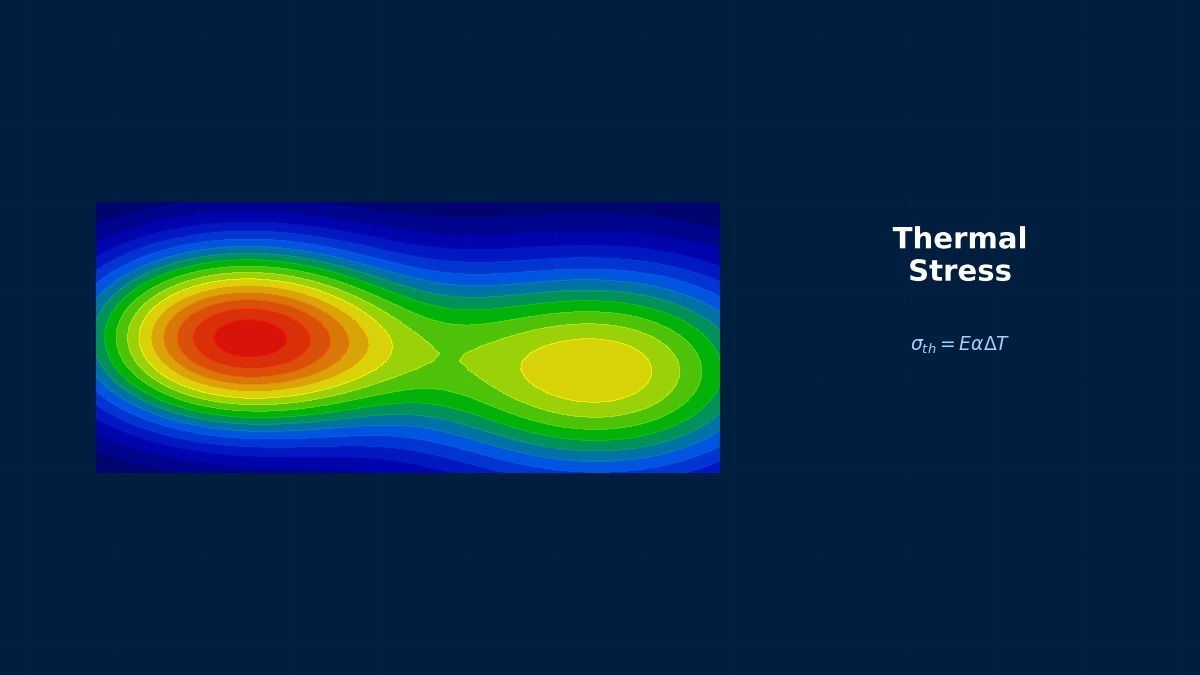
Theory: expansion mismatch shears the solder
Overview
On an automotive board only the solder of large chip parts cracked. Why are bigger parts more vulnerable?
As temperature rises, the board (about 17 ppm/K) expands more than the component (about 6.5 ppm/K for ceramic). Relative to the component centre, the mismatch displacement grows with distance, so the outermost solder is sheared most. Larger parts have longer distances to their corners and larger shear. Solder is a soft metal that creeps even at low temperature, so it absorbs this shear every cycle, fatiguing gradually as cracks grow. Life depends on the strain; doubling strain cuts life to roughly a fifth. Component size, joint height and temperature range therefore govern life.
Engelmaier's model
F is a correction factor (1), L_D distance from component centre to corner, Δα expansion mismatch (10.5 ppm/K), h joint height (0.1 mm), ε_f' fatigue ductility coefficient (0.325), T̄_sj mean joint temperature and f cycles per day.
Surface mount and fatigue-life models
As surface mounting spread in the 1980s, soldering parts directly to the board surface exposed joints to expansion mismatch directly, unlike leaded parts, and opens under temperature cycling became a major issue. Engelmaier then built a solder-life model from the Coffin–Manson low-cycle fatigue law, including temperature range, component size and cycle rate. After the move to lead-free solders material constants were revised, and finite-element methods that compute strain energy are now widely used.
Worked examples
Example 1: component size and life (0.1 mm joint)
| Component | L_D | −40 to 125 °C: strain | −40 to 125 °C: life | 0 to 100 °C: strain | 0 to 100 °C: life |
|---|---|---|---|---|---|
| 0603 (1.6×0.8 mm) | 0.89 mm | 1.55% | 4,390 | 0.94% | 5,784 |
| 1206 (3.2×1.6 mm) | 1.79 mm | 3.10% | 814 | 1.88% | 1,252 |
| 2512 (6.4×3.2 mm) | 3.58 mm | 6.20% | 151 | 3.76% | 271 |
−40 to 125 °C is cycled once an hour (24 per day) and 0 to 100 °C twice a day; exponent c is −0.411 and −0.453 respectively.
Example 2: joint height and life (1206, −40 to 125 °C)
| Joint height | Life |
|---|---|
| 0.05 mm | 151 |
| 0.10 mm | 814 |
| 0.20 mm | 4,390 |
Doubling component size cuts life to a fifth.
Strain scales with L_D and doubles; life scales with strain to the power 1/c (c about −0.41), so it falls by 2 to the power 2.4, about a fifth. Likewise halving joint height doubles strain and cuts life to a fifth, so large parts and low-standoff parts (such as bottom-terminated components) need special care. The model estimates strain from simple geometry and omits actual shape, fillet geometry and board warpage. It's handy for early comparisons, but where life requirements are strict, as in automotive, finite-element analysis including solder creep computes strain energy per cycle for test-calibrated life models.
Reliability assessment workflow
- Define temperature range, mean temperature and cycles per day in service.
- Compare component lives with Engelmaier's model to flag risky parts.
- For risky parts, compute strain energy by FE including solder creep.
- Estimate failure probability over life with test-calibrated models.
- Compare countermeasures: joint height, board material, underfill.
“Only the large resistors opened”
In an automotive control unit, partway through temperature-cycle testing only the solder of 2512 current-sense resistors cracked and opened; smaller parts on the same board were fine. Engelmaier's model showed 2512 life about one-thirtieth of 0603's, so failure within the test count was unsurprising. Splitting each resistor into two smaller parts of equivalent value and increasing solder volume for more height let the board pass the full test.
Common mistakes
Mistakes and fixes
| Mistake | Effect | Fix |
|---|---|---|
| Using small parts as representative | Large parts fail | Assess per part |
| Elastic solder model | Wrong strain | Include creep |
| Confusing test and field conditions | Wrong life conversion | Derive acceleration factors |
| Ignoring board warpage | Strain underestimated | Analyse the whole board |
| Reusing tin–lead constants | Wrong lead-free life | Material-specific constants |
I'd like to learn related topics.
Related pages include creep–fatigue interaction, CTE-gradient design, thermal residual stress, bimetallic strips and thermal assembly.
Related Topics
Experience the theory firsthand with interactive simulators in this field
All Simulators