Notch Fatigue (Notch Effect)
Notch Fatigue (Notch Effect): Theoretical Foundations
Notch Effect
Professor, how do we evaluate fatigue at notches?
Notches (holes, fillets, grooves) significantly reduce fatigue life due to stress concentration. The relationship between the theoretical stress concentration factor $K_t$ and the fatigue notch factor $K_f$ is important.
$q$ is the notch sensitivity (depends on material and notch radius, 0~1). Higher strength materials have $q \to 1$.
Notch Stress in FEM
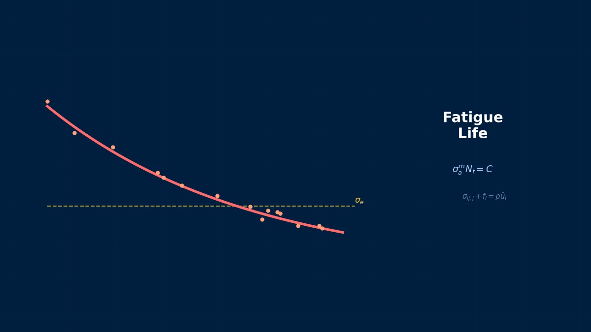
FEM directly calculates notch stress including $K_t$. This stress is evaluated using an S-N curve (notch stress-based).
Neuber's Rule
Neuber's rule estimates elastoplastic local strain from elastic FEM stress:
$K_\sigma$ is the stress concentration factor, $K_\varepsilon$ is the strain concentration factor. Estimates local strain without elastoplastic FEM.
Summary
Neuber's Kt-Kf Problem
The ratio (sensitivity factor q) between the theoretical stress concentration factor Kt and the fatigue notch factor Kf varies with material strength and notch dimensions. For high-strength steel (1500MPa class), q≈1.0 (Kt and Kf are almost equal), but for mild steel, q≈0.6. Neuber (1936) explained this difference is due to the stress gradient at the notch root, and this forms the basis of current ISO/ASME standards for structural strength design.
Computational Methods for Notch Fatigue (Notch Effect)
FEM for Notch Fatigue
Two approaches:
1. Direct Approach — Elastoplastic FEM → local strain → Coffin-Manson
2. Neuber Approach — Elastic FEM → Neuber's rule to estimate local strain → Coffin-Manson
Fatigue software (nCode, fe-safe) supports both approaches.
Summary
Practical Estimation Formula for Notch Fatigue Limit
Peterson's formula (Kf=1+q(Kt-1)) is widely used to estimate notch fatigue limits. q is a parameter representing the material's "gradient sensitivity", increasing with higher tensile strength. For tool steel SUJ2 (Rm=2200MPa), q=0.98, while for S45C (Rm=700MPa), q=0.75, resulting in Kf differences from 1.5 to 2.1 for a notch depth of 1mm and r=0.5mm.
Notch Fatigue (Notch Effect) in Practice
Notch Fatigue in Practice
Essential for fatigue evaluation of bolt holes, fillets, keyways, and weld toes.
Practical Checklist
Crack Prevention Measures for Press Dies
Fatigue failure at notch areas (corner R) in press dies directly leads to production stoppage. In practice, ensure a minimum curvature radius r≥0.5mm, verify stress concentration at the notch root via FEM, then perform life evaluation using the Kf method. Denso Corporation standardized FEM + notch fatigue analysis in die design around 2015, improving die life by 1.5x compared to conventional methods.
Notch Fatigue (Notch Effect): Software & Solver Comparison
Tools
Simulation Driven Design with OptiStruct
Altair OptiStruct has a Fatigue Quick Setup feature that automatically calculates Kf for notch fatigue evaluation. Through collaboration with HBM-Prenscia, it directly links with fe-safe, enabling fatigue evaluation of all components including notches in suspension arm shapes in a single flow. BMW shortened the design verification period for a new suspension by 3 months using this flow.
Advanced Technology
Advanced Notch Fatigue (Notch Effect): Modern Research & Trends in Notch Fatigue
Taylor's Theory at the Notch Tip
Taylor's cylinder (critical distance) theory evaluates fatigue based on stress at a point distance L away from the notch tip. L is material-dependent, approximately 0.1mm for high-strength steel, 0.1~1mm for cast iron. More accurate than traditional evaluation using total stress concentration, and its concept is incorporated into ASTM E739.
Notch Fatigue (Notch Effect): Common Issues & Debugging
Notch Fatigue Troubleshooting
Discrepancy Between FEM Stress Concentration and Actual Measured Life
When there's a large difference between Kt calculated by FEM and Kf obtained from tests, surface roughness effects are suspect. For turned surfaces (Ra=1.6μm), finishing
Related Topics
Experience the theory firsthand with the interactive simulator for this field
All Simulators