Electromagnetic Field Simulation of Axial Flux Motors
Theory: flux direction and the torque-producing surface
Overview
For an electric-motorcycle in-wheel motor, a thin disc-type axial flux motor is a candidate. How does it differ from an ordinary motor?
An ordinary (radial flux) motor has a cylindrical rotor surrounded by the stator, with flux running radially. In an axial flux motor, rotor and stator are discs facing each other along the shaft, with flux parallel to it. Torque comes from tangential force on the gap surface times radius, so the large outer radius does most of the work. In a thin, wide space an axial machine gains both area and radius.
Estimating torque
$\sigma$ is the average shear stress on the gap surface (tangential magnetic force per area), typically tens of kPa depending on cooling. In an axial machine the annulus from $R_i$ to $R_o$ produces torque; in a radial machine the cylinder of rotor radius $r$ and stack length $L$. Axial torque scales with the cube of outer radius.
Magnetic attraction
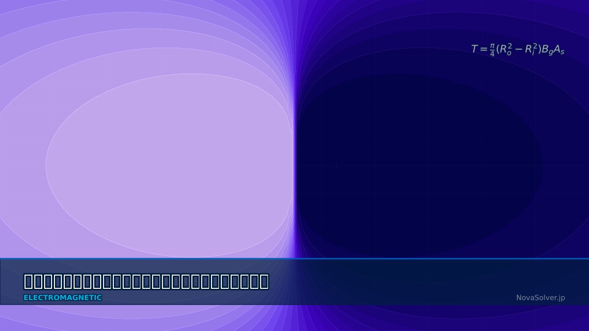
$B_g$ is gap flux density and $A$ the facing area. Magnets and stator iron attract strongly; in radial machines these forces cancel around the circumference, but in axial machines they appear directly as axial force. Sandwiching a rotor between two stators, or a stator between two rotors, balances the two sides.
The first motors were discs
Faraday's electromagnetic rotation of 1821 and his disc generator of 1831 (the Faraday disc) were in fact axial arrangements: a disc spinning in a magnetic field. Cylindrical radial machines, easy to build from stacked laminations, later became dominant, and axial designs were long confined to niche uses. Since the 2000s — with high-performance rare-earth magnets, soft-magnetic composites and lamination techniques for complex cores, and 3D electromagnetic analysis — they have returned to prominence in electric vehicles and aircraft that need light, thin motors.
Worked examples
Example 1: torque at 200 mm diameter
An illustrative example to show trends. Gap shear stress is 25 kPa; the axial machine has two gaps (one stator between two rotors), and the radial machine has a 70 mm rotor radius inside a 200 mm stator.
| Type | Condition | Torque |
|---|---|---|
| Axial (2 gaps) | Inner ratio 0.5 | 91.6 N·m |
| Axial (2 gaps) | Inner ratio 0.6 | 82.1 N·m |
| Axial (2 gaps) | Inner ratio 0.7 | 68.8 N·m |
| Radial | Stack 60 mm | 46.2 N·m |
| Radial | Stack 100 mm | 77.0 N·m |
| Radial | Stack 150 mm | 115.5 N·m |
If the stack can be long, the radial machine gives more torque.
Right. Here the radial stack matches the axial 82 N·m at about 107 mm. So axial machines pay off where axial length is short and diameter large — inside a wheel, or at an aircraft propeller hub. A smaller inner ratio adds area and torque, but leaves less room for windings at the inner radius and limits current, so the optimum ratio accounts for winding space too (around 0.6 is a common guide).
Example 2: axial attraction
| Gap flux density | Magnetic pressure | Force on annulus (200 mm OD, ratio 0.6) |
|---|---|---|
| 0.7 T | 195 kPa | 3.9 kN |
| 0.9 T | 322 kPa | 6.5 kN |
| 1.1 T | 481 kPa | 9.7 kN |
A single gap pulls with enough force to lift a car. Even in balanced double-sided designs, if the gaps become 0.8 mm and 1.2 mm, a simple estimate with 5 mm magnets and 1.2 T remanence gives about a 13% difference between the sides — a net force approaching 1 kN. Assembly tolerance, disc stiffness and bearing capacity must be set using electromagnetic and structural analysis together.
How to approach the analysis
Analysis methods
- 3D electromagnetic analysis: flux runs axially and pole width and speed vary with radius, which a 2D section can't capture; 3D is the baseline.
- Quasi-3D methods: slice radially into several cylindrical sections, solve each as a 2D linear machine and sum them; useful for fast early comparisons.
- Structural and thermal coupling: disc deflection under attraction changes the gap, torque and force; cooling a thin stator is hard.
“The disc rubbed when it spun”
A prototype axial flux motor was fine at rest, yet after assembly the rotor rubbed the stator when spun. The cause was disc deflection under magnetic attraction: magnet area and force are largest near the rim, and a cantilevered disc deflects most there too. Even 0.1 mm is a large fraction of a gap around 1 mm, and a narrower gap increases attraction further. The check is iterative: pass electromagnetic forces to a structural analysis, then solve the electromagnetics again with the deformed gap.
Common mistakes
Mistakes and fixes
| Mistake | Effect | Fix |
|---|---|---|
| 2D section only | Wrong torque and loss | 3D or quasi-3D |
| Ignoring axial force | Bearing damage, rubbing | Check with magnetic pressure |
| Ignoring gap variation | Net force remains | Analyse with tolerances |
| Inner ratio by area only | Windings don't fit | Optimise including winding space |
| Leaving cooling for later | Thin stator overheats | Do thermal analysis concurrently |
I'd like to try motor torque and design myself.
Try the electric motor design tool for motor design, the motor torque calculator for torque and the motor drives tool for drives. Related design topics are covered in PMSM design, surface PM motors, cogging torque and motor thermal analysis.
Related Topics
Experience the theory firsthand with the interactive simulator for this field
All Simulators