Radiation View Factor Calculation
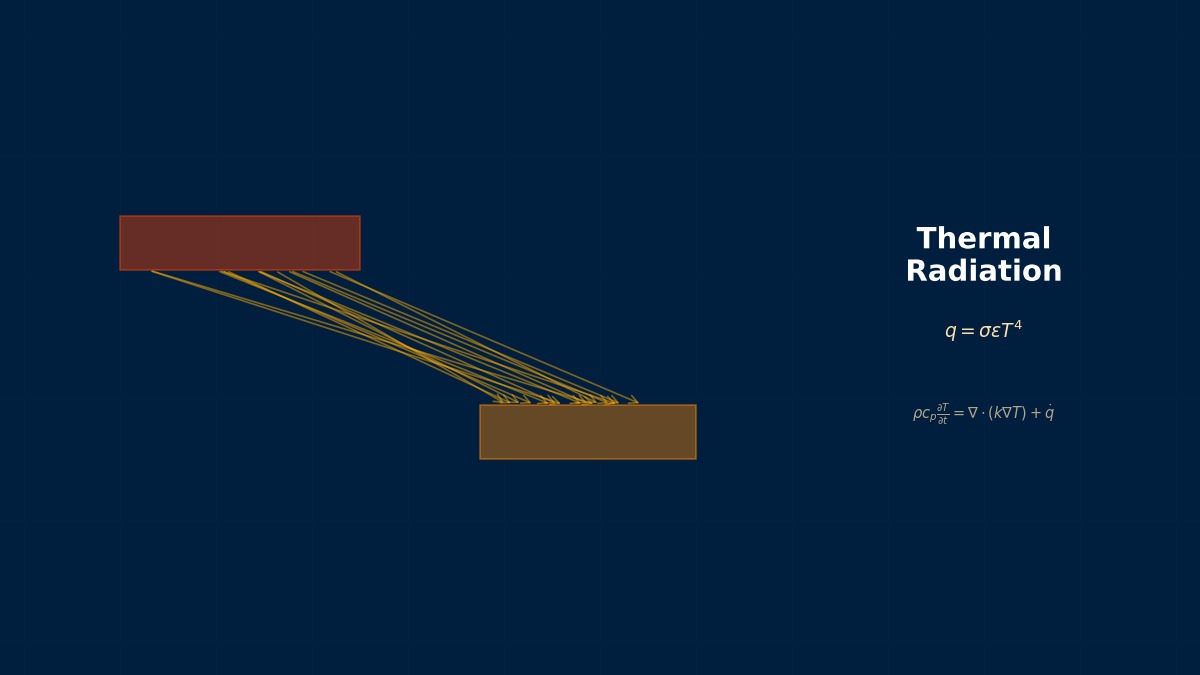
Theory: how much one surface “sees” another
Overview
When I run radiation analyses, the view-factor calculation takes ages up front. What is it actually computing?
It's the fraction of radiation leaving one surface that lands directly on another. It depends only on geometry — not on temperature or emissivity — so once computed it can be reused for any temperatures. But with $n$ surfaces there are $n^2$ pairs, so the work balloons for models with many faces.
Definition
$\theta_1$ and $\theta_2$ are the angles between the line joining the two elements and each surface normal, and $R$ is their distance. Diffuse surfaces (radiating equally in all directions) are assumed.
Reciprocity and summation
With these two rules many view factors follow without any integration — inside a closed sphere, for example, the factor from anywhere to any patch is just the area ratio. Checking that computed factors satisfy the summation rule is also a quick test of a numerical calculation.
Lighting and radiation shared the same calculation
The idea behind view factors was used early in lighting engineering to calculate illuminance. In the 1980s it was carried into computer graphics as the radiosity method, which rendered the soft shading produced by light bouncing repeatedly between the walls of a room. The approach is essentially the same as solving surface-to-surface exchange as simultaneous equations in thermal radiation — a clear case of the same mathematics crossing fields.
Worked example: exact formulas versus numerical methods
Facing squares
View factor between two parallel, aligned squares of side $a$ at distance $L$ (exact formula):
| a/L | View factor | Interpretation |
|---|---|---|
| 0.5 | 0.069 | Far away, looks small |
| 1 | 0.200 | 1 m square 1 m away |
| 2 | 0.415 | — |
| 5 | 0.690 | — |
| 10 | 0.827 | Closely spaced parallel plates |
Two 1 m² black surfaces at 500 K and 300 K facing each other 1 m apart exchange about 616 W. As the gap closes, the view factor approaches 1, the infinite-parallel-plate limit.
Error of Monte Carlo ray tracing
Rays are launched from random points in cosine-weighted random directions and the fraction hitting the other surface is counted. Since each ray is a hit or a miss, the scatter follows the formula below. For squares with $a = L$ ($F = 0.200$), a home-made calculation agreed closely.
| Rays | Scatter (standard deviation) |
|---|---|
| 1,000 | ±6.3 % |
| 10,000 | ±2.0 % |
| 100,000 | ±0.63 % |
| 1,000,000 | ±0.20 % |
Error of area-subdivision integration
The defining double integral was approximated by dividing each face into $n \times n$ patches and summing between centroids, for two perpendicular squares sharing an edge (exact value 0.2000):
| Subdivision | View factor | Error |
|---|---|---|
| 2 × 2 | 0.264 | +32 % |
| 4 × 4 | 0.233 | +16.5 % |
| 8 × 8 | 0.217 | +8.4 % |
| 16 × 16 | 0.208 | +4.2 % |
| 32 × 32 | 0.204 | +2.1 % |
Doubling the subdivision only halves the error.
Right next to the shared edge the distance $R$ goes to zero and the integrand blows up. Well-separated faces need few patches, but where surfaces meet — inside corners of an enclosure, the roots of fins — error lingers. Commercial codes handle this by refining or integrating analytically for close pairs, but depending on the settings they may compute coarsely, so watch for it.
Use in thermal analysis
Key settings
- Obstruction: other parts between two faces reduce their view factor. Turning off shadowing speeds up the calculation but overestimates exchange in cluttered geometry.
- Summation check: in an enclosure, confirm each face's factors sum to 1. Faces that deviate significantly need finer subdivision or more rays, or radiation is leaking through gaps.
- Radiation to the surroundings: for open geometry, add a virtual surface representing the environment (sky, room walls) or apply radiation to an ambient temperature as a boundary condition.
- Surface coarsening: radiation rarely needs the fine thermal mesh. Use features that agglomerate faces for radiation to cut the view-factor workload.
Choosing the method
| Method | Strength | Caution |
|---|---|---|
| Exact formulas (tables) | Simple shapes, verification | Limited geometries |
| Area-subdivision integration | Well-separated faces, smooth results | Errors near touching faces |
| Monte Carlo | Complex geometry, shadowing, specular reflection | Statistical scatter; enough rays needed |
Suspect the view factor before the emissivity
When a thermal model with radiation disagrees with measurements, the temptation is to tweak emissivity. Yet catalogue emissivities are often not far off, and the cause frequently lies with the view factors instead — radiation leaking through gaps, shadowing switched off, nearby parts omitted. Checking view factors with the summation rule and a simple exact case before tuning emissivity usually turns out to be the faster route.
Common mistakes
Mistakes and fixes
| Mistake | Effect | Fix |
|---|---|---|
| Using one direction without reciprocity | Exchange between unequal areas is wrong | Check with $A_1F_{12} = A_2F_{21}$ |
| Switching off shadowing | Exchange overestimated in cluttered geometry | Compute with shadowing and compare |
| Coarse subdivision of touching faces | View factors overestimated | Refine near corners or integrate analytically |
| Leaving the ray count at default | Large scatter on small faces | Size the ray count from the accuracy needed on key faces |
| No surroundings in open geometry | Radiation has nowhere to go; temperatures are wrong | Add a virtual enclosure or ambient temperature |
I'd like to try view factors for other shapes.
With the view factor simulator you can change sizes and distances and see how the view factor responds. Exchange among several surfaces can be explored with the radiation network simulator, and ray tracing with the Monte Carlo radiative transfer simulator. The theory continues in the articles on the radiosity method, grey-body exchange and Monte Carlo radiation analysis.
Related Topics
Experience the theory firsthand with the interactive simulator for this field
All Simulators