Rectangular Plate Navier Solution (Four-Edge Simply Supported)
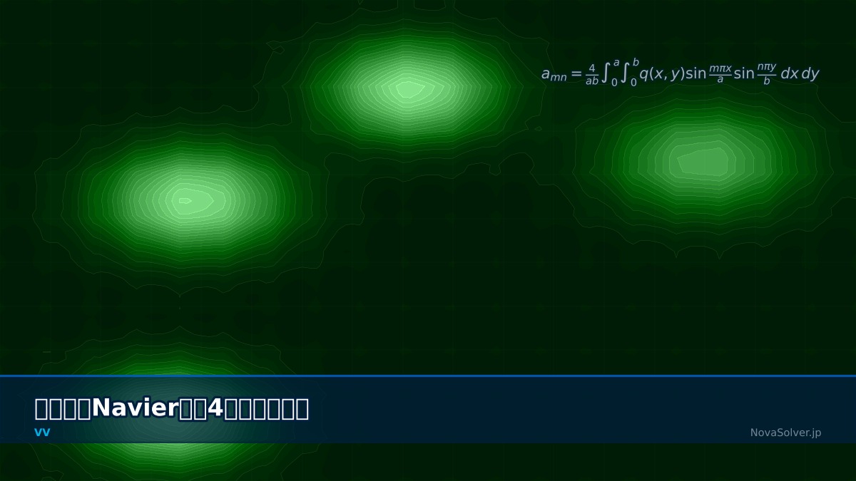
Theory: an exact double Fourier series solution
Overview
I've built an FEM model with shell elements. How can I check the results are right?
For plate bending, the classic first check is the Navier solution. A rectangular plate simply supported on all four edges under uniform load was solved exactly by Navier in 1820 with a double Fourier series. Because the answer is known precisely, it tests element type, mesh density and boundary conditions all at once — an ideal warm-up before a production model.
Governing equation and solution
This is Kirchhoff thin-plate theory; $D$ is the flexural rigidity and $h$ the thickness. For an $a \times b$ plate simply supported on all edges under uniform load $q_0$, products of sines satisfy the boundary conditions automatically and the solution is the following series (odd $m, n$ only):
Coefficient table (Poisson's ratio 0.3)
| Aspect ratio b/a | Deflection α | Moment β (short span) |
|---|---|---|
| 1.0 | 0.00406 | 0.0479 |
| 1.5 | 0.00772 | 0.0812 |
| 2.0 | 0.01013 | 0.1017 |
| 3.0 | 0.01223 | 0.1189 |
$a$ is the short side. As the aspect ratio grows the plate approaches a beam spanning the short direction ($\alpha = 5/384 \approx 0.01302$, $\beta = 1/8$).
Navier was trying to build a bridge
Claude-Louis Navier is best known for the Navier–Stokes equations, but by profession he was a bridge engineer, and his 1820 plate analysis grew out of that work. His suspension bridge over the Seine in Paris, however, was dismantled in 1826, close to completion, after a foundation problem. It is still cited as a reminder that theoretical accuracy and real-world success are different things. An analytical solution checks whether a model is built correctly; it does not guarantee a design is safe.
Worked example: series and mesh convergence
How many terms are enough
| Terms (max m, n) | α | β |
|---|---|---|
| 1 | 0.004161 (+2.4 %) | 0.05338 (+11.5 %) |
| 3 | 0.004055 | 0.04692 |
| 5 | 0.004064 | 0.04823 |
| 9 | 0.004062 | 0.04797 |
| 19 | 0.004062 | 0.04788 |
| Converged | 0.004062 | 0.04789 |
Deflection settles by about five terms, but the moment takes much longer.
The moment is a second derivative of deflection, so each term picks up a factor of $m^2$ or $n^2$ and higher terms matter more. Shear force, a third derivative, converges even more slowly. FEM behaves the same way: on the same mesh, deflection may be right while stress has not yet converged. Always compare both deflection and stress when verifying.
Steel plate example
A 1 m × 1 m steel plate 10 mm thick ($E = 206$ GPa, $\nu = 0.3$) under 5 kPa gives $D \approx 18{,}900$ N·m, a centre deflection of about 1.08 mm (11% of the thickness) and a maximum bending stress of about 14 MPa. The deflection is small relative to the thickness, so linear thin-plate theory applies.
Mesh convergence with finite differences
A simply supported plate can be split into two Poisson equations. Solving the square plate with finite differences on an $N \times N$ grid and comparing the centre deflection coefficient with the converged value:
| Grid | α | Error |
|---|---|---|
| 4 × 4 | 0.004028 | −0.84 % |
| 8 × 8 | 0.004055 | −0.19 % |
| 16 × 16 | 0.004061 | −0.04 % |
| 32 × 32 | 0.004062 | −0.01 % |
Each doubling of the grid cuts the error to about a quarter, as expected for a second-order method. With FEM too, checking how the error falls over three or more meshes tells you whether the elements are working properly.
Pitfalls when comparing with FEM
Applying the simple support
- Constrain only the out-of-plane displacement $w = 0$ along the edges. Constraining edge rotation turns it into a clamped plate and the deflection drops to roughly 0.3 times.
- Constrain in-plane displacement only as much as needed to stop rigid-body motion. Fixing in-plane displacement along whole edges creates membrane forces as the plate deflects, which distorts results, especially at larger deflections.
- In the Navier solution, concentrated downward reactions develop at the four corners; without them the corners would lift. If the FEM support is modelled as compression-only contact, the corners lift and the result no longer matches.
Choosing elements and thickness
- Shear locking: fully integrated linear elements become far too stiff for thin plates and badly underestimate deflection. Use reduced-integration or locking-free formulations.
- Thick plates: the Navier solution is thin-plate theory, so once the thickness exceeds about a tenth of the span, FEM (Mindlin theory) shows extra deflection from shear deformation. Use a thin plate for the comparison.
- Large deflection: once deflection reaches a sizeable fraction of the thickness, membrane action makes the true deflection smaller than the linear solution. Compare linear with linear and assess nonlinear effects separately.
Verification procedure
- Build a square plate about 1/100 of the span thick, constrain only $w = 0$ on all four edges, and apply uniform load.
- On three or more meshes, compare centre deflection and bending moment (or surface stress) with the coefficient table.
- Once both deflection and stress converge to within 1–2%, carry the same element type and mesh density into the production model.
Most “stress mismatches” are about where you read it
Shell stresses are computed at element centres or integration points, and nodal values are often averaged from neighbouring elements. If no node sits exactly at the plate centre, or you compare nodally averaged contours, the same model can differ by a few percent. The coefficient $\beta$ refers to the plate centre at the surface, so match the location (centre), the face (top or bottom) and the averaging method when comparing.
Common mistakes
Mistakes and fixes
| Mistake | Effect | Fix |
|---|---|---|
| Constraining edge rotation | The plate becomes clamped; deflection about 0.3× | Constrain $w = 0$ only |
| Fully integrated linear elements | Shear locking makes the plate too stiff | Reduced-integration or locking-free elements |
| Judging convergence on deflection only | Stress still unconverged | Check stress on three meshes too |
| Comparing with a thick plate | Differences from shear deformation | Use thickness around 1/100 of the span |
| Using a table for a different Poisson's ratio | Moments off by a few percent | Compute coefficients with the material's $\nu$ |
I'd like to know other verification problems too.
For an axisymmetric case use bending of a circular plate, and for a one-dimensional one the simply supported beam benchmark. Plate buckling can be explored with the plate buckling calculator and laminate stiffness with the composite laminate plate analyzer.
Related Topics
Experience the theory firsthand with the interactive simulator for this field
All Simulators