CAE Analysis of Parabolic Reflector Antennas
Theory: bigger aperture, sharper beam
Overview
Satellite TV dishes are about 45 cm across, but satellite ground stations are several metres. What does size change?
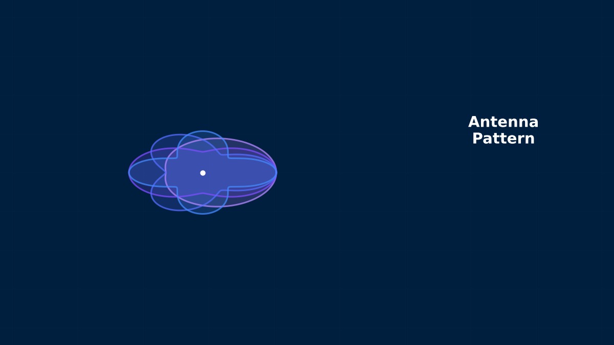
A parabolic dish reflects waves from a feed (such as a horn) at its focus into a parallel beam. Performance depends on how many wavelengths across the aperture is. A larger aperture squeezes the beam narrower and raises gain — how strongly it radiates in one direction. Ground stations are large because they must capture weak signals and avoid picking up neighbouring satellites, which requires a narrow beam.
Gain, beamwidth and far-field distance
$\eta$ is aperture efficiency, set by feed illumination taper, spillover past the reflector and blockage by the feed and struts; typically about 0.55–0.75. $\theta_{3dB}$ is the half-power beamwidth and $R_{ff}$ the far-field distance, which grows with antenna size and matters for measurement and analysis.
Surface accuracy and Ruze's equation
$\varepsilon$ is the RMS deviation from the ideal paraboloid. Deviations scramble the phase of reflected waves and reduce gain. The loss grows with the square of frequency, so higher frequencies demand tighter surfaces.
From Hertz's experiment to radio telescopes
In 1888 Hertz already used a parabolic-cylinder reflector to concentrate waves in the experiments that confirmed electromagnetic radiation. Reflector antennas developed rapidly for radar during World War II, and radio astronomy inherited them afterwards. In the 1960s radio telescopes tens of metres across were built one after another, and controlling surface distortion from self-weight, wind and sunlight became a major challenge. “Homologous design” — structures that, though deformed by gravity, deform into another paraboloid — was one answer.
Worked examples
Example 1: gain by aperture and frequency
With aperture efficiency 0.65:
| Frequency | Diameter | Gain | Beamwidth | Far-field distance |
|---|---|---|---|---|
| 12 GHz | 0.6 m | 35.7 dBi | 2.9° | 29 m |
| 12 GHz | 1.2 m | 41.7 dBi | 1.5° | 115 m |
| 12 GHz | 3.0 m | 49.7 dBi | 0.58° | 720 m |
| 30 GHz | 1.2 m | 49.7 dBi | 0.58° | 288 m |
| 30 GHz | 3.0 m | 57.6 dBi | 0.23° | 1,800 m |
At 3 m and 30 GHz the far field starts 1.8 km away.
Yes. So large antennas are measured either on long outdoor ranges or with near-field measurement, which samples the field close by and transforms it to far-field behaviour. In analysis too, far-field formulas apply only beyond this distance. And a 0.23° beamwidth is so narrow that a 0.1° pointing error costs significant gain, so deflection of the support structure under wind and temperature feeds straight into gain — one reason electromagnetic and structural analysis are evaluated together.
Example 2: loss from surface error
| RMS surface error | 12 GHz | 30 GHz | 90 GHz |
|---|---|---|---|
| 0.2 mm | 0.04 dB | 0.27 dB | 2.5 dB |
| 0.5 mm | 0.27 dB | 1.7 dB | 15 dB |
| 1.0 mm | 1.1 dB | 6.9 dB | — |
The same 0.5 mm distortion hardly matters at 12 GHz but costs about 30% of the gain at 30 GHz and most of it at 90 GHz. Moving to higher frequency requires revisiting both manufacturing accuracy and deformation from gravity, wind and temperature.
Example 3: focal length and dish depth
| f/D | Focal length (1.2 m) | Dish depth |
|---|---|---|
| 0.25 | 0.30 m | 300 mm |
| 0.40 | 0.48 m | 188 mm |
| 0.60 | 0.72 m | 125 mm |
A deep dish (small f/D) keeps the feed close but needs a feed pattern covering wide angles. A shallow dish (large f/D) eases feed design but lengthens the struts. Feed pattern and reflector shape are chosen together.
How to approach the analysis
Choosing methods
| Part | Method | Reason |
|---|---|---|
| Feed horn | FEM, method of moments | Wavelength-sized; fine detail matters |
| Reflector | Physical optics (PO) | Tens of wavelengths across |
| Edge diffraction, sidelobes | PO with diffraction corrections | Captures wide-angle radiation |
| Surface deformation | Structural analysis → PO | Pass the deformed shape to EM |
Cautions
- Blockage: feed and struts obscure part of the aperture, lowering gain and raising sidelobes; include them.
- Feed displacement: moving off focus misaligns phase, steering the beam or reducing gain.
- Sidelobe regulations: satellite links limit sidelobes to prevent interference with neighbouring satellites.
“Performance drops only on sunny afternoons”
Large reflector antennas sometimes lose signal level only on sunny afternoons: sunlight warms one side of the reflector and thermal expansion distorts the surface. On a dish tens of metres across, a few kelvin of temperature difference can distort the surface by around a millimetre, costing several dB at high frequency. Radio telescopes counter this with temperature sensing and actuated surface panels, and with choices of structural materials and paint — a textbook case for coupled thermal, structural and electromagnetic evaluation.
Common mistakes
Mistakes and fixes
| Mistake | Effect | Fix |
|---|---|---|
| Assuming 100% efficiency | Gain overestimated by about 2 dB | Evaluate taper, spillover, blockage |
| Far-field formula at short range | Wrong pattern | Check 2D²/λ |
| Ignoring surface deformation | Gain shortfall at high frequency | Feed structural deformation to PO |
| Full-wave FEM of everything | Intractable computation | Combine with PO |
| Omitting strut blockage | Sidelobes underestimated | Model the struts |
I'd like to try gain and link calculations myself.
Try the antenna gain calculator for gain, the Friis transmission tool for link budgets and the radiation pattern simulator for radiation patterns. Feeds are covered in horn antennas, fundamentals in gain and directivity and radiation patterns, and electronic beam steering in beamforming.