Impact Damage Analysis of Composite Materials
Impact Damage Analysis of Composite Materials: Theoretical Foundations
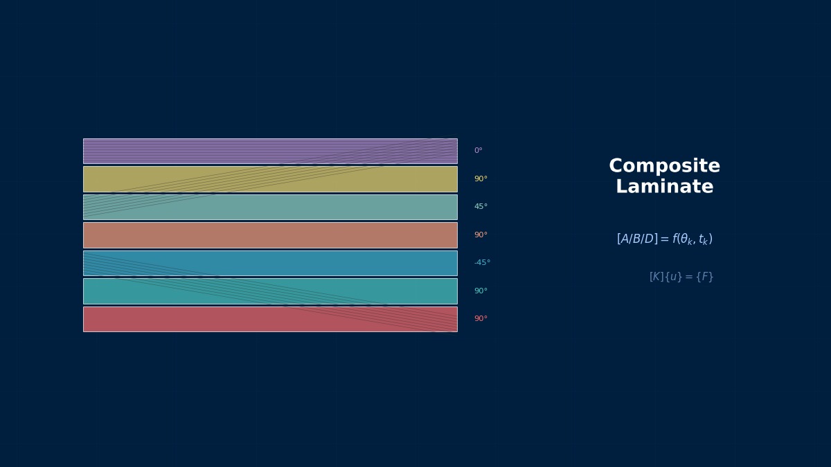
Composite Material Impact Damage
Professor, what happens when composite materials are impacted?
Metals dent (plastic deformation) upon impact, but composite materials experience internal damage propagation. While there may be almost no visible trace on the surface, extensive internal matrix cracking, delamination, and fiber breakage occur internally.
That's BVID (Barely Visible Impact Damage), right?
Correct. In aircraft design, BVID (Barely Visible Impact Damage, difficult to detect visually) is the most stringent design condition. BVID occurs from tool drops (low-velocity impact), and the residual strength under compressive load after impact (CAI) determines the design allowable value.
Impact Classification
| Type | Velocity | Example | Primary Damage |
|---|---|---|---|
| Low-Velocity Impact | < 10 m/s | Tool drop, hailstone | Matrix cracking, delamination |
| Medium-Velocity Impact | 10~100 m/s | Runway debris, bird strike | Penetration damage, extensive delamination |
| High-Velocity Impact | > 100 m/s | Ballistic impact | Penetration, plug formation |
| Hyper-Velocity Impact | > 1000 m/s | Space debris | Cratering, complete destruction |
Low-velocity impact is the most common and the cause of BVID, right?
Low-velocity impact occurs most frequently during aircraft operation. Design assumes BVID for impacts of specific energy (e.g., 35 J/Boeing, 50 J/Airbus) based on ICAO/FAA regulations.
Impact Damage Mechanism
Low-velocity impact damage mechanism (chronological):
1. Contact Initiation — Impactor contacts the plate
2. Matrix Cracking Initiation — Cracks form in orthogonal directions due to bending stress
3. Delamination Propagation — Matrix cracks reach the interface, causing delamination
4. Fiber Breakage — If energy is high, fibers also break
5. Rebound — Impactor bounces back. Damage remains
So delamination starts from matrix cracks.
When a matrix crack reaches the interface, delamination occurs if the energy at the crack tip exceeds the interlaminar fracture toughness. Delamination preferentially occurs at interfaces with different fiber angles (e.g., 0°/90° interface).
FEM for Impact Analysis
Impact analysis typically uses the Explicit Method. In Abaqus/Explicit or LS-DYNA:
- Impactor — Rigid or elastic body
- Plate — Solid elements + Hashin damage + CZM (interlaminar)
- Contact — General Contact or Penalty method
Do we need to include CZM for all layers?
Ideally yes, but computational cost becomes enormous. Placing CZM only at critical interfaces (where fiber angle changes abruptly) is practical.
Summary
Let me summarize the theory of composite material impact damage.
Key points:
- BVID — Internal damage invisible from the surface. The most stringent condition in aircraft design
- Damage Chain — Matrix cracking → delamination → fiber breakage
- Low-velocity impact is most common — Tool drops, hail, runway debris
- Simulate with Explicit Method — Hashin + CZM
- Delamination preferentially occurs at interfaces with abrupt fiber angle changes
Bird Strike Testing and the History of CFRP Impact Design
Bird strike testing for CFRP structures in aircraft is mandated by US FAR 25.571, assuming a 1.8kg bird impact at 270km/h. When CFRP began to be used in the 1970s, its impact characteristics were considered significantly inferior to metals. However, through laminate design optimization and impact after strength (CAI: Compression After Impact) optimization, it has been demonstrated that the current A350 wing has superior impact resistance compared to aluminum.
Computational Methods for Impact Damage Analysis of Composite Materials
FEM Model for Impact Analysis
Please tell me the specific settings for impact analysis.
Typical low-velocity impact model in Abaqus/Explicit:
Model Configuration
- Impactor: Rigid sphere (radius 12.5 mm, mass 3 kg, initial velocity 5 m/s → energy 37.5 J)
- Plate: Solid elements (C3D8R). Each layer 0.125 mm. 24 layers = 3 mm thickness
- CZM: Cohesive elements (COH3D8) placed at critical interfaces
- Contact: General Contact (automatic full-surface contact)
Mesh
- Around impact point: 0.5~1 mm elements
- Remote areas: 2~5 mm elements
- Through-thickness direction: 1 element per layer (solid) + CZM between layers
24 layers with 1 element each and CZM for all layers... that's a huge number of elements.
For a 20×20 mm refined zone around the impact area, it's about 500,000 elements. Computation time ranges from several hours to one day (can be accelerated with GPU).
Damage Evaluation
Result verification items:
- Force-Time Curve — Time history of contact force on the impactor. Peak force and contact duration
- Energy-Time Curve — Absorbed energy. Calculation of coefficient of restitution
- Damage Area — Projected area of delamination. Comparison with C-scan
- Damage Variables per Layer — Contours of Hashin's $d_{ft}, d_{mt}$
Comparing the damage area with C-scan is the key for validation, right?
Yes. If the FEM delamination area and the ultrasonic C-scan delamination area agree within 30%, the prediction is considered good. The shape (elliptical or peanut-shaped) is also compared.
Summary
Let me organize the numerical methods for impact analysis.
Key points:
- Abaqus/Explicit + C3D8R + Hashin + CZM — Standard configuration
- 1 element per layer + CZM between layers — Detailed model
- Verify with force-time, energy-time curves — Compare with experiment
- Compare damage area — FEM vs. C-scan. Good if within 30%
- High computational cost — 500k elements. Consider GPU utilization
CAI (Compression After Impact) Evaluation Procedure
CAI (Compression After Impact) is one of the most important characteristics in CFRP design. ASTM D7137 specifies impact with a 16mm diameter indenter at a specific energy (6.7J/mm), followed by compression testing of the same specimen to measure residual strength. CAI curves are obtained by varying impact energy, confirming that CAI at barely visible impact damage (BVID) exceeds the allowable compressive strength.
Related Topics
Experience the theory firsthand with the interactive simulator for this field
All Simulators