NAFEMS LE5: Torsion of a Z-Section Cantilever Beam
NAFEMS LE5: Theoretical Foundations
Overview
Teacher! Today's topic is NAFEMS LE5: Torsion of a Z-section cantilever beam, right? What is it about?
The NAFEMS LE5 benchmark. A shear load is applied at the end of a Z-section cantilever beam. It validates the warping torsion stress in thin-walled sections. The reference solution is σ_xx = -108MPa.
Governing Equations
Discretization Method
How do you actually solve these equations on a computer?
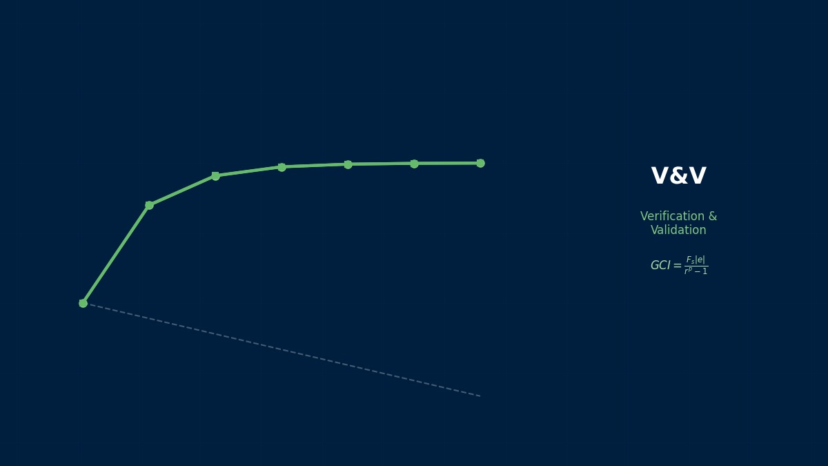
We use spatial discretization by the Finite Element Method (FEM). We assemble the element stiffness matrices and construct the global stiffness equation.
We perform a transformation to the weak form (variational form) and use the Galerkin method formulation with test functions and shape functions. The choice of element type (low-order elements vs. higher-order elements, full integration vs. reduced integration) directly affects the trade-off between solution accuracy and computational cost.
Matrix Solution Algorithms
What exactly are matrix solution algorithms?
We solve the system of equations using direct methods (LU decomposition, Cholesky decomposition) or iterative methods (CG method, GMRES method). Preconditioned iterative methods are effective for large-scale problems.
| Solver | Classification | Memory Usage | Applicable Scale |
|---|---|---|---|
| LU Decomposition | Direct Method | O(n²) | Small to Medium Scale |
| Cholesky Decomposition | Direct Method (Symmetric Positive Definite) | O(n²) | Small to Medium Scale |
| PCG Method | Iterative Method | O(n) | Large Scale |
| GMRES Method | Iterative Method | O(n·m) | Large Scale / Non-symmetric |
| AMG Preconditioner | Preprocessing | O(n) | Very Large Scale |
So, if you cut corners on the finite element method part, you'll pay for it later. I'll keep that in mind!
Implementation in Commercial Tools
So, what software can be used to do NAFEMS LE5: Torsion of a Z-section cantilever beam?
| Tool Name | Developer/Current | Main File Formats |
|---|---|---|
| MSC Nastran / NX Nastran | MSC Nastran (Hexagon), NX Nastran (Siemens Digital Industries Software) | .bdf, .dat, .f06, .op2, .pch |
| Abaqus FEA (SIMULIA) | Dassault Systèmes SIMULIA | .inp, .odb, .cae, .sta, .msg |
| Ansys Mechanical (formerly ANSYS Structural) | Ansys Inc. | .cdb, .rst, .db, .ans, .mac |
| COMSOL Multiphysics | COMSOL AB | .mph |
Vendor Lineage and Product Integration History
Does each software have a dramatic origin story?
MSC Nastran / NX Nastran
Next is about MSC Nastran, right? What's the story?
Developed in the 1960s as NASA Structural Analysis (NASTRAN). Commercialized by MSC Software, later UGS (now Siemens) derived NX Nastran. MSC was acquired by Hexagon AB in 2017.
Current Affiliation: MSC Nastran (Hexagon), NX Nastran (Siemens Digital Industries Software)
Abaqus FEA (SIMULIA)
What exactly is Abaqus FEA?
Developed in 1978 by HKS (Hibbitt, Karlsson & Sorensen). Acquired by Dassault Systèmes in 2005 and integrated into the SIMULIA brand.
Current Affiliation: Dassault Systèmes SIMULIA
Wait, wait, structural analysis... so, can it also be used for cases like this?
Ansys Mechanical (formerly ANSYS Structural)
Tell me about "Ansys Mechanical"!
Developed in 1970 by Swanson Analysis Systems Inc. (SASI). Based on APDL (Ansys Parametric Design Language).
Current Affiliation: Ansys Inc.
Wow, the structural analysis talk is super interesting! Tell me more.
File Formats and Interoperability
Are there any points to note when transferring data between different software?
| Format | Extension | Type | Overview |
|---|---|---|---|
| STEP | .stp/.step | Neutral CAD | 3D CAD data exchange format compliant with ISO 10303. Supports geometry + PMI. |
| IGES | .igs/.iges | Neutral CAD | Early CAD data exchange standard. Has compatibility issues with surface data. Transition to STEP is progressing. |
| VTK | .vtk/.vtu | Visualization | Visualization Toolkit format. Used by ParaView, etc. |
When converting models between different solvers, attention must be paid to the correspondence of element types, compatibility of material models, and differences in the representation of loads and boundary conditions. Particularly, higher-order elements and special elements (cohesive elements, user-defined elements, etc.) often cannot be directly converted between solvers.